Fluorescence microscope and observation method using the same

a fluorescence microscope and microscope technology, applied in the field of fluorescence microscope and method of observing samples using the microscope, can solve the problems of reducing the contrast of a formed fluorescence image, difficulty in precise registration of weak fluorescence, and difficulty in using an objective lens b>20/b> having a high numerical aperture, so as to reduce the required work space, efficient block unnecessary fluorescence, and simplify the effect of the apparatus

Active Publication Date: 2007-11-20
KOREA ELECTROTECH RES INST
View PDF6 Cites 22 Cited by
  • Summary
  • Abstract
  • Description
  • Claims
  • Application Information

AI Technical Summary

Benefits of technology

[0021]Accordingly, the present invention has been made keeping in mind the above problems occurring in the prior art, and an object of the present invention is to provide a fluorescence microscope and method of observing samples using the microscope, which can reduce optical noise and obtain more highly sensitive images, thus obtaining precise information about the density, quantity, location, etc. of a fluorophore, and which can simultaneously process separate images even when a plurality of fluorophores having different excitation and fluorescent wavelength ranges is distributed, thus easily obtaining pieces of information about the fluorophores.
[0022]Another object of the present invention is to provide a biochip observation apparatus, which is constructed to be able to observe a small amount of fluorescent dye due to the reduction of the occurrence of optical noises and to simultaneously observe fluorescence images emitted from various fluorescent dyes without using optical filters, in order to solve another disadvantage of conventional apparatuses for observing micro-objects such as biochips in that, as various optical noises must be eliminated and various types of optical filters must be used, observation apparatuses become complicated and the size thereof increases.
[0023]A further object of the present invention is to provide a fluorescence microscope, which is constructed to excite micro-objects distributed within a region having a relatively high volume in addition to a monolayer, thus acquiring a fluorescence image with high sensitivity from the excited micro-objects, unlike the above-described conventional fluorescence microscopes using an evanescent wave.
[0027]Further, in accordance with another aspect of the present invention, there is provided a fluorescence microscope, comprising an objective lens; a first medium unit with a refractive index of n1 for accommodating one or more micro-objects including fluorophores and providing a path of excitation light to excite the fluorophores; a fourth medium unit with a refractive index of n4 for covering a surface facing the objective lens among surfaces of the first medium unit; and a third medium unit with a refractive index of n3 placed between the fourth medium unit and the objective lens to totally reflect the excitation light incident through the first and fourth medium units at an interface of the third medium unit coming into contact with the fourth medium unit.
[0034]The fluorescence microscope of the present invention is constructed to separate the paths of excitation light and fluorescence emission by exploiting an excitation scheme using total internal reflection (total reflection) so as to observe the fluorescence of a micro sample, such as a biochip, and constructed to irradiate the excitation light from a side opposite to an objective lens and an optical processing unit around a sample, thus efficiently blocking unnecessary fluorescence and scattering occurring on the objective lens, etc. due to the irradiation of excitation light, reducing a required work space between the objective lens and the sample. The fluorescence microscope of the present invention is constructed to allow only fluorescence emission to reach an observation unit, such as an optical processing unit, so that an excitation light blocking filter, a shielding filter, etc. are unnecessary, thus greatly simplifying the apparatus and realizing high sensitivity.
[0035]Further, the fluorescence microscope of the present invention is constructed to utilize the above-described space excitation scheme, so that the sensitivity of a small amount of fluorescence generated from micro-objects, such as biochips, can greatly increase, and constructed not to utilize optical filters, so that polychromatic fluorescent dyes can be simultaneously observed on a single screen, thus further simplifying observation equipment and increasing observation efficiency.

Problems solved by technology

These optical noises decrease the contrast of a formed fluorescence image, and causes difficulty in the precise registration of weak fluorescence, generated due to a small amount of fluorophore present in the micro-object to be observed.
However, in this scheme, a considerable available space S is required between the objective lens20 and the object 25, which causes the use of an objective lens 20 having a high numerical aperture to be difficult.
Moreover, there is a problem in that light scattered from the object 25 (including dust) and several surfaces of the microscope is incident on the objective lens 20, so that it is difficult to prevent the occurrence of optical noise.
However, since the intensity of the evanescent wave is low as described above, there is a problem in that the sensitivity of detected light is excessively low, and only micro-objects existing around the interface are consistently observed.
Accordingly, this method is problematic in that it is not suitable for the observation of micro-objects distributed within a region having a relatively high volume.
Further, since the above fluorescence observation system requires components such as a color filter for selecting an optical spectrum, it is impossible to perform an operation of simultaneously processing separate florescent images using color images and obtaining information about the separate images in the case where a plurality of fluorophores having different excitation and fluorescence wavelength ranges are distributed.
However, there are problems in that, since the intensity of the evanescent wave is low as described above, the sensitivity of detected light is excessively low, and only micro-objects existing around an interface are consistently observed.
Accordingly, the above microscopes have a problem in that they are not suitable for the observation of micro-objects distributed within a region having a relatively high volume.

Method used


Image

  • Fluorescence microscope and observation method using the same
  • Fluorescence microscope and observation method using the same
  • Fluorescence microscope and observation method using the same

Examples


Embodiment Construction

[0047]Hereinafter, embodiments of the present invention will be described in detail with reference to the attached drawings.

[0048]Reference now should be made to the drawings, in which the same reference numerals are used throughout the different drawings to designate the same or similar components.

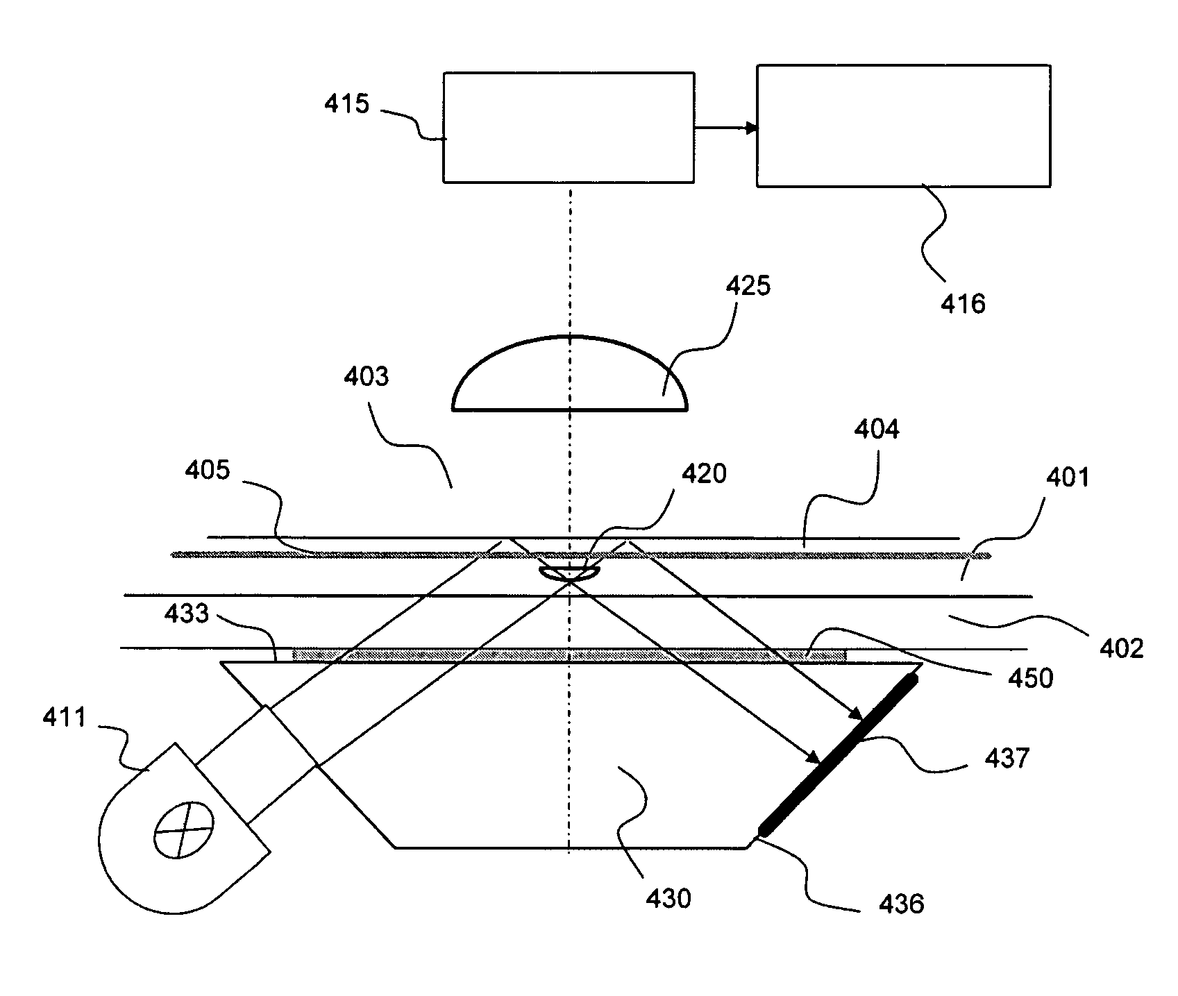
[0049]FIG. 7 illustrates the detailed construction of a fluorescence microscope according to an embodiment of the present invention. As shown in FIG. 7, micro-objects (organic molecules, fibroid materials, deoxyribonucleic acid (DNA), chromosomes, cells, etc.), which are to be observed and include fluorophores, are included in a first medium 301 having a refractive index of n1. A second medium 302 having a refractive index of n2 is placed to be adjacent to one surface of the first medium 301 and to support the bottom of the first medium. The refractive index n2 of the second medium 302 can be adjusted to be equal to or similar to the refractive index n1 of the first medium 301, but it is ...


PUM

PropertyMeasurementUnit
penetration depthaaaaaaaaaa
poweraaaaaaaaaa
poweraaaaaaaaaa

Abstract

The present invention relates, in general, to a fluorescence microscope and method of observing samples using the microscope and, more particularly, to a fluorescence microscope and method of observing samples using the microscope, which can reduce optical noise and obtain images with higher sensitivity, thus obtaining precise information about the density, quantity, location, etc. of a fluorophore, and which can simultaneously process separate images even when a plurality of fluorophores having different excitation and fluorescent wavelength ranges is distributed, thus easily obtaining information about the fluorophores. The fluorescence microscope of the present invention includes an objective lens, and first and third medium units. The first medium unit has a refractive index of n1 to accommodate one or more micro-objects including fluorophores and provide a path of excitation light to excite the fluorophores. The third medium unit has a refractive index of n3, and is placed between the first medium unit and the objective lens to totally reflect the excitation light incident through the first medium unit at an interface of the third medium unit coming into contact with the first medium unit. The refractive indices of the third and first medium units satisfy a relationship of n1>n3.

Description

BACKGROUND OF THE INVENTION[0001]1. Field of the Invention[0002]The present invention relates, in general, to a fluorescence microscope and method of observing samples using the microscope and, more particularly, to a fluorescence microscope and method of observing samples using the microscope, which can reduce optical noise and obtain images with higher sensitivity, thus obtaining precise information about the density, quantity, location, etc. of a fluorophore, and which can simultaneously process separate images even when a plurality of fluorophores having different excitation and fluorescent wavelength ranges is distributed, thus easily obtaining information about the fluorophores.[0003]The present invention relates, in general, to a fluorescence microscope, which is an optical instrument, and more particularly, to technology used to observe micro-samples in detail using fluorescence in a variety of biomedical fields, including the fluorescence analysis of a biochip, such as a DN...

Claims


Application Information

Patent Timeline
Patent Type & Authority Patents(United States)
IPC IPC(8): F21V9/16F21K2/00G01C19/66G01J1/00G01N21/41G02B21/06G01T1/10G02B21/16
CPCG02B21/16G02B21/06
Inventor KANG, UKPAPAYAN, GARRY V.
Owner KOREA ELECTROTECH RES INST
Why Eureka
Try Eureka