
Oxy-fuel combustion process

a combustion process and oxyfuel technology, applied in the direction of combustion types, separation processes, lighting and heating apparatuses, etc., can solve the problems of increasing heat loss, nitrogen oxides (nox), and nox, and not benefiting the combustion process

Inactive Publication Date: 2007-12-04
BOC GRP INC
View PDF55 Cites 17 Cited by
  • Summary
  • Abstract
  • Description
  • Claims
  • Application Information

AI Technical Summary

Benefits of technology

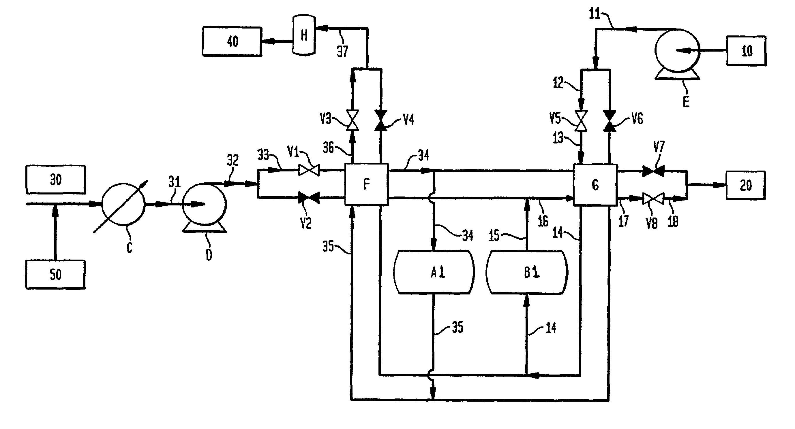
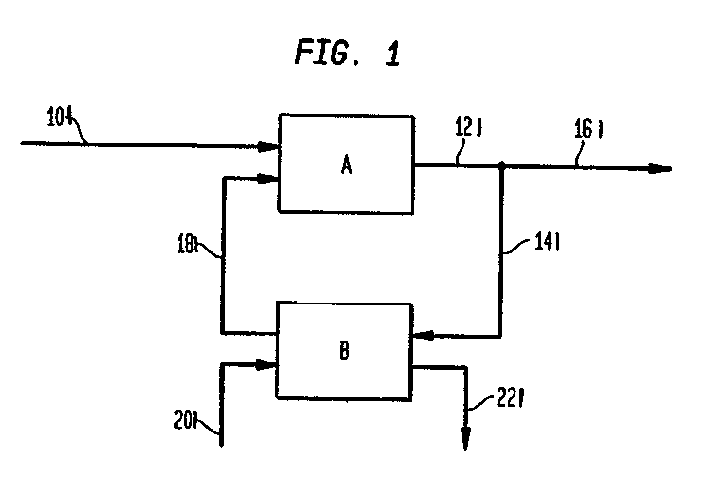
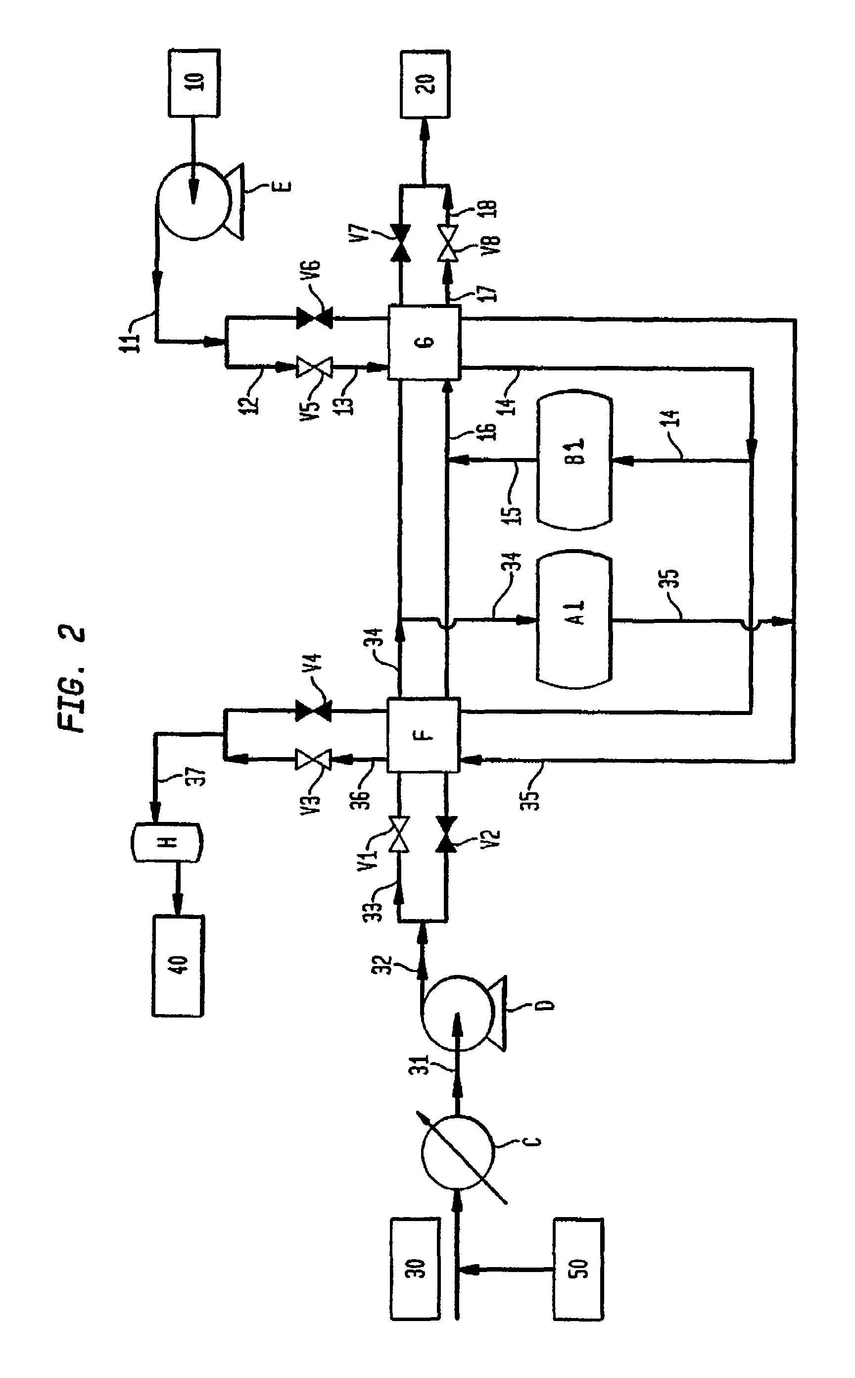
"The present invention is directed to a method for forming a product gas stream for use in an oxygen consuming process. The method involves cyclically feeding air and an oxygen selective mixed conductor, wherein oxygen is retained on the conductor and the reactor is at a temperature greater than 300°C. The oxygen-depleted gas stream, which is substantially free of nitrogen, is then fed to the reactor to form the product gas stream. The product gas stream is then used in the oxygen consuming process. The method can be performed with a single reactor or multiple reactors, and it can be thermally self-sustaining. The method produces nitrogen-rich gas and carbon dioxide as by-products. The invention also includes a method for forming a gas stream using a boiler as the oxygen consuming process. The methods can be applied to various other oxygen consuming processes such as hydrocarbon oxidation, chemical oxidation, combustion, and gasification."

Problems solved by technology

The presence of nitrogen in air does not benefit the combustion process and may even create problems.
For example, nitrogen will react with oxygen at combustion temperatures forming nitrogen oxides (NOx), an undesirable pollutant.
Moreover, the presence of nitrogen increases the flue gas volume which in turn increases the heat losses and decreases the thermal efficiency of the combustion process.
Additionally, high nitrogen content in the flue gas may make it unattractive to capture CO2 either as a product or for sequestration.
However, combustion with oxygen generates very high temperatures and therefore some of the flue gas produced must be recycled to moderate temperatures.
While such a scheme would eliminate the problems associated with nitrogen, the cost of oxygen at present is too high to make it economically attractive.
The disadvantages of this method of oxygen production are the high cost of fabrication of the membrane and the difficulty in producing membrane structures that are leak-proof.
Also, oxygen recovery is typically low in membrane units.
Thus, the process can be commercially adopted more easily compared to the membrane based process mentioned above, which requires special fabrication, sealing and assembly procedures, and is known to have several issues in this regard.

Method used


Image

  • Oxy-fuel combustion process
  • Oxy-fuel combustion process
  • Oxy-fuel combustion process

Examples


example 1

Preparation of La0.2Sr0.8Co0.6Fe0.4O3−δ Perovskite Powder

[0065]The powder of perovskite-type oxide was prepared first by mixing of corresponding metal oxides or hydroxides and then repeated steps of sintering, ball-milling and filtration for three times. The temperatures in 3 sintering steps were, respectively, 900° C., 950° C. and 1000° C., and the sintering time was 8 hours. The first sintering was conducted right after dry-mixing of La2O3, Sr(OH)2.8H2O, Ni2O3, Co2O3 and Fe2O3. The ball milling of the material was carried out with grinding media and water after each sintering. The solid was collected by filtration after ball milling. The filtration cake was dried at 100° C. for overnight before it was subjected to the next sintering. After the last ball-milling, the dried filtration cake was crushed and ground into fine powder. The final powder had a perovskite-type phase structure.

example 2

Fabrication of La0.2Sr0.8Co0.6Fe0.4O3−δ Perovskite Extrudates

[0066]The perovskite-type oxide powder made in Example 1 was transformed into a slurry after addition of about 5 wt % hydroxyethyl cellulose and 14.5 wt % water. Thus obtained slurry was aged overnight before it was loaded into an extruder and transformed into extrudates (3 mm in diameter and 4 mm in length). The extrudates were dried in an oven at 90° C. for about 2 hr, and then calcined at 600° C. for 5 hr. The extrudates were finally sintered at 1050° C. for 8 h. The final extrudates were porous and mechanically strong.

example 3

[0067]The extrudates made in Example 2 were packed in a tubular reactor made of high temperature metal alloy. The reactor was designed in such a way that the gas streams of air, CO2 and steam could be fed into the reactor from either the top end or the bottom end of the reactor as required. Mass flow controllers controlled the flow rates of the gas streams. The reactor temperature and valves were controlled with PLC. The product and waste streams during purge and retention steps were collected in a tank, and their average compositions were analyzed with a gas analyzer and a GC. In the experiment, the reactor temperature was controlled at 825° C. An air stream at 7.6 slpm and a CO2 stream at 4.7 slpm were alternately fed into the reactor for every 30 seconds in a counter-current fashion. The reactor pressures were kept at 23.7 psia and 18.7 psia respectively during air and CO2 steps. During the last 2 seconds of the air step, the reactor pressure decreased from 23.7 psia to 18.7 psia...


PUM

PropertyMeasurementUnit
temperatureaaaaaaaaaa
temperaturesaaaaaaaaaa

Abstract

Production of oxygen-enriched gas streams is disclosed herein. Air streams contact an oxygen-selective mixed conductor particularly a perovskite material whereby oxygen is retained or adsorbed on the perovskite and can be employed in a variety of processes such as in combusting a fuel gas, heat recovery and boiler related operations.

Description

[0001]This application claims priority from U.S. patent application Ser. No. 10 / 313,876 filed Dec. 6, 2002 now abandoned, which claims priority from Provisional U.S. Patent Applications 60 / 346,582 filed Jan. 8, 2002; 60 / 346,597 filed Jan. 8, 2002; and 60 / 347,268 filed Jan. 10, 2002.BACKGROUND OF THE INVENTION[0002]The primary purpose of combustion processes is to generate heat. In a power plant or in an industrial boiler system, the heat is utilized to generate high pressure steam which in turn may be used to provide process heating or may be used to produce electricity. Most conventional combustion processes utilize air as a source of oxygen. The presence of nitrogen in air does not benefit the combustion process and may even create problems. For example, nitrogen will react with oxygen at combustion temperatures forming nitrogen oxides (NOx), an undesirable pollutant. In many cases, the products of combustion must be treated to reduce nitrogen oxide emissions below environmentally...

Claims


Application Information

Patent Timeline
Patent Type & Authority Patents(United States)
IPC IPC(8): B01D53/04C01B13/02F23C9/00F23L7/00
CPCB01D53/04C01B13/0259F23C9/00F23L7/007Y10S502/525B01D2253/10B01D2256/12B01D2257/102B01D2259/40001C01B2210/0046F23C2202/30F23L2900/07001Y02E20/322Y02E20/344B01D53/047Y02E20/32Y02E20/34Y02P20/10
Inventor ZENG, YONGXIANACHARYA, DIVYANSHU R.TAMHANKAR, SATISH S.RAMPRASAD, NARAYANANRAMACHANDRAN, RAMAKRISHNANFITCH, FRANK R.MACLEAN, DONALD L.LIN, JERRY Y. S.CLARKE, RICHARD H.
Owner BOC GRP INC
Learn More