Nuclear medical imaging device

a technology of medical imaging and nucleus, applied in the field of medical imaging, can solve the problems of reducing the exposure of an imaged subject to x-ray, blurring and noise in conventional x-ray cat devices, and reducing the x-ray exposure of an imaged subject, so as to achieve accurate correction of attenuation factors and increase the emission imaging time

Inactive Publication Date: 2007-12-18
HIGHBROOK HLDG
View PDF53 Cites 10 Cited by
  • Summary
  • Abstract
  • Description
  • Claims
  • Application Information

AI Technical Summary

Benefits of technology

[0010]Apparatus according to the present invention allows x-ray transmission imaging of a subject, such as x-ray CAT scanning, to be performed along with emission imaging such as gamma imaging. The x-ray imaging allows attenuation properties of the subject to be determined, and these can be used to correct emission imaging techniques, such as SPECT. Transmission and emission images of the subject can be obtained concurrently, so that the emission image can be accurately corrected for attenuation factors. X-ray imaging is typically performed with high x-ray flux levels, whereas gamma imaging typically is performed at much lower flux levels. However, x-ray transmission and emission images can be formed over similar imaging time spans, as measured from the start of image data collection to the end of image data collection, using a pulsed x-ray source with a low duty cycle (time on divided by time off). The duty cycle can be as low as 1%, or less, for example 0.1%. For example, an x-ray image can be reconstructed from scans or sections obtained during the shorter “on” times of the x-ray source, with the emission images built up during the longer “off” times. If emission imaging is not performed while the x-ray source is “on”, this approach increases the emission imaging time by a factor related to duty cycle. However, as the duty cycle of the x-ray source is low, this factor may be insignificant.
[0011]An improved x-ray transmission imaging technique is also described, in which a plurality of x-ray sources, source apertures, and detector apertures are moved in coordinated manner so that x-ray beams remain in register through the source and detector apertures during a scanning process. This approach gives improved efficiency. Further, the use of narrow x-ray beams, which are substantially non-divergent over the field of view of the apparatus, reduces x-ray exposure of an imaged subject. A further advantage of non-divergent beams is increased resolution of the x-ray imaging. Low energy x-rays are typically scattered more, and cause blurring and noise problems in conventional x-ray CAT devices. Using conventional x-ray sources, it is difficult to hold a constant high voltage for pulsed operation, leading to a mixture of high energy x-rays with low energy x-rays that cause scattering-related noise problems. The use of source and detector aperture collimated x-ray beams reduces this problem significantly. The use of vanes can further improve performance, as more fully described in our co-pending application U.S. patent application Ser. No. 10 / 933,036.
[0012]However, by using a detector aperture to define a narrow beam, such scattered x-rays do not pass through the detector aperture, reducing noise and increasing resolution. A narrow beam, which in this example is a beam having a diameter of less than 5 mm, such as between approximately 1 mm and approximately 1.5 mm, also allows use of a high photon flux with detectors capable of handling a high photon flux while concurrently performing emission imaging with detectors having a relatively low count rate capability. The detector aperture may be approximately the same dimension as the source aperture, within the plane of an image slice (such as using similar slot widths), so as to collimate the transmitted beam and avoid any substantial beam divergence through the field of view.

Problems solved by technology

However, as the duty cycle of the x-ray source is low, this factor may be insignificant.
Further, the use of narrow x-ray beams, which are substantially non-divergent over the field of view of the apparatus, reduces x-ray exposure of an imaged subject.
Low energy x-rays are typically scattered more, and cause blurring and noise problems in conventional x-ray CAT devices.
Using conventional x-ray sources, it is difficult to hold a constant high voltage for pulsed operation, leading to a mixture of high energy x-rays with low energy x-rays that cause scattering-related noise problems.
The imaging time may be longer than conventional apparatus, but the cost of such an instrument can be a small fraction of conventional apparatus.

Method used


Image

  • Nuclear medical imaging device
  • Nuclear medical imaging device
  • Nuclear medical imaging device

Examples


Embodiment Construction

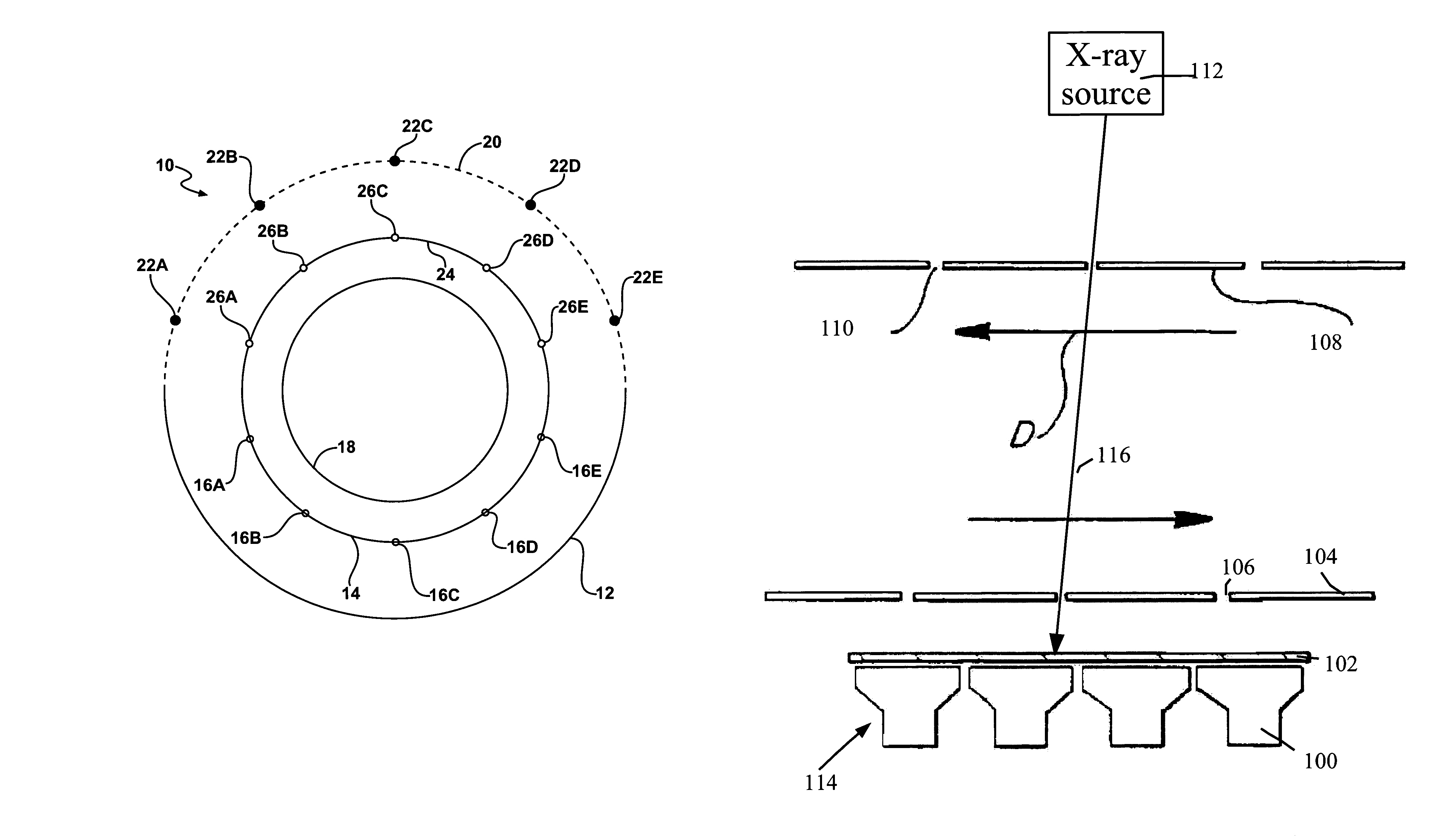
[0037]Embodiments of the present invention provide an improved imaging of a subject. Imaging may be carried out using two electromagnetic wavelength regions, such as x-ray imaging and gamma imaging (such as SPECT). X-ray attenuation measurements can be used to provide an improved SPECT image, by allowing correction for attenuation variability of the gamma photons in a subject. The attenuation coefficient may be assumed to be the same for gamma photons or x-ray photons, or a model of the subject used to convert between attenuation coefficients so as to make an attenuation correction.

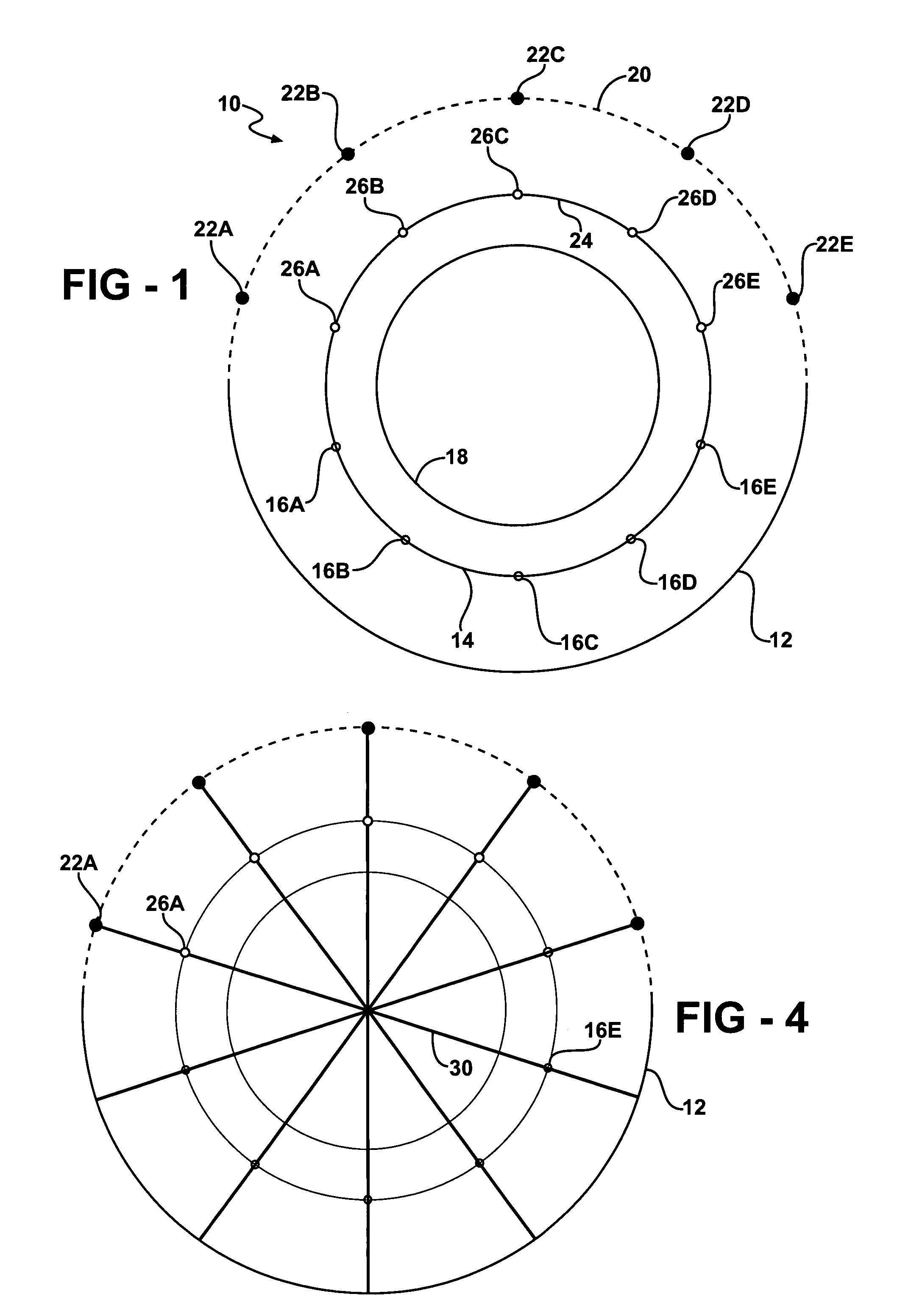
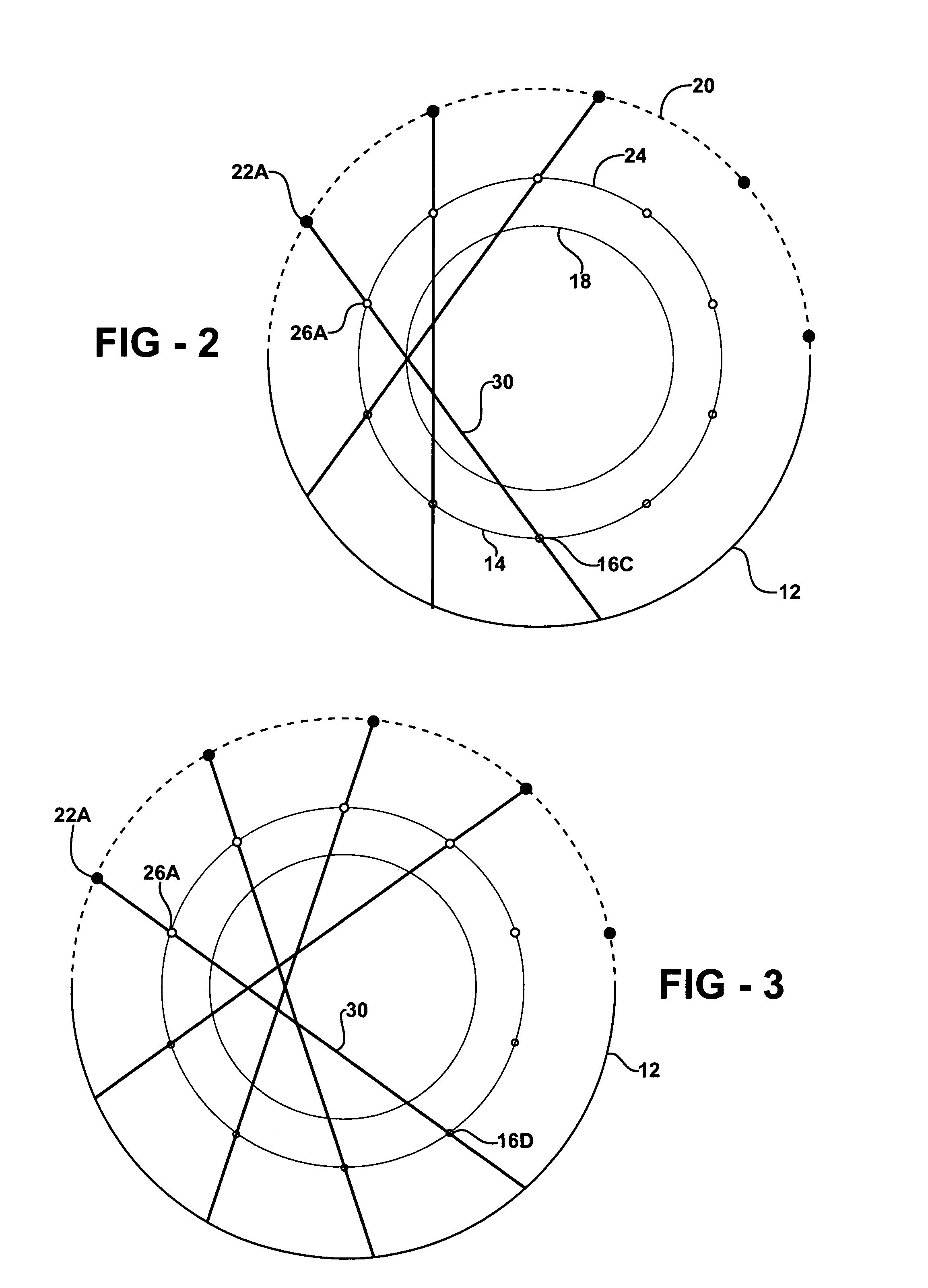
[0038]In representative embodiments of the present invention, attenuation measurements are carried out by determining attenuation of a radiation beam through the subject. A radiation source is located adjacent a field of view, and radiation from the radiation source is detected after being transmitted through the field of view. By varying the path direction of the radiation through the field of view, a ra...


PUM

PropertyMeasurementUnit
diameteraaaaaaaaaa
diameteraaaaaaaaaa
diameteraaaaaaaaaa

Abstract

An apparatus for imaging a field of view, according to an embodiment of the present invention, comprises an x-ray source positioned adjacent to the field of view, a source mask located between the x-ray source and the field of view having at least one source aperture defined therethrough, and an emission detector, such as a gamma camera, adjacent to the field of view. The apparatus may allow substantially concurrent x-ray imaging and gamma imaging of the field of view.

Description

REFERENCE TO RELATED APPLICATIONS[0001]This application claims priority of U.S. Provisional Patent Application Ser. No. 60 / 607,319, filed Sep. 3, 2004, and 60 / 652,424, filed Feb. 11, 2005, the entire content of both of which are incorporated herein by reference.FIELD OF THE INVENTION[0002]The present invention relates to generally to apparatus and methods of imaging, and in particular to medical imaging.BACKGROUND OF THE INVENTION[0003]Medical imaging devices take a variety of forms, including nuclear medical imaging devices such as described in Applicant's co-pending patent applications, the entire contents of which are incorporated herein by reference. As known to those of skill in the art, when using nuclear medical imaging devices, such as SPECT devices, it is desirable to determine the amount of radiation attenuation attributable to the portions of the subject surrounding the area being imaged.[0004]SPECT (Single Photon Emission Computed Tomography) allows imaging of a subject ...

Claims


Application Information

Patent Timeline
Patent Type & Authority Patents(United States)
IPC IPC(8): G01N23/04G01T1/166G21K1/02
CPCA61B6/037G01T1/1615G01T1/1648G01T1/1611A61B6/032A61B6/4035A61B6/541
Inventor JUNI, JACK E.
Owner HIGHBROOK HLDG
Why Eureka
Try Eureka