Device and method for increasing mass transport at liquid-solid diffusion boundary layer

a technology of diffusion boundary layer and liquid solid, which is applied in the direction of hydrogen/synthetic gas production, chemical/physical/physical-chemical stationary reactors, energy-based chemical/physical/physical-chemical processes, etc., can solve the problems of high capital cost, waste of a large percentage of fluid energy used for circulating fluid, etc., and achieve the effect of increasing mass or energy transpor

Inactive Publication Date: 2007-12-25
ENTEGRIS INC
View PDF7 Cites 0 Cited by
  • Summary
  • Abstract
  • Description
  • Claims
  • Application Information

AI Technical Summary

Benefits of technology

[0007]The present invention is directed to an apparatus for controlling the fluid flow at the interface between a substrate and a fluid by utilizing a membrane to create a thin film of fluid on the substrate. The device may be used to control the transfer of mass or energy between the substrate and the fluid. Preferably the apparatus is used to increase the mass transport from a substrate to a fluid at the solid-fluid diffusion boundary layer. The apparatus and method may be used for increasing the mass transport rate of a chemical process at the solid and fluid interface in a fluid cell. The device includes a membrane in close contact with surface of a substrate or work piece, to separate the process cell into two chambers, so that the fluid velocity at the work piece is controlled separately from the main cell flow. The diffusion boundary layer at the work piece is controlled and minimized by the rate that fluid is withdrawn from the work piece chamber or through a port in the work piece.
[0009]One embodiment of the present invention is an apparatus that includes a porous membrane proximate to and covering a substrate. The apparatus has a port that is also covered by the porous membrane. Fluid flow through the porous membrane cause a thin layer of fluid to flow between the substrate and the porous membrane and through the apparatus port. The flow of fluid flow between the substrate and membrane modifies the state of the fluid by transfer of mass and or energy with the substrate. The membrane may be flexible or bonded to a member which allows flexibility so that the membrane remains proximate to the substrate as the substrate changes shape. The substrate may be an electrode, a chemical reagent, a heat exchange element, a chiller, a catalyst, or a combination of these. The apparatus may further include a base for supporting the substrate. The base may have a port that is in fluid communication with the port in the substrate; the base port is also covered or enclosed by the porous membrane.
[0010]One embodiment of the invention includes a flexible convoluted member sealed to the porous membrane. The convoluted member forms a fluid tight seal with the base and maintains the porous membrane proximate to the substrate during fluid flow and changes in shape of the substrate. Another embodiment of the invention includes the use of a loose drainage material between the substrate and the porous membrane for maintaining the porous membrane proximate to the substrate surface and controlling the thickness of flow of fluid in contact with the substrate.
[0011]One embodiment of the present invention is a method for increasing mass or energy transport at liquid-solid diffusion boundary layer of a work piece that has at least one surface in contact with a liquid. The method includes providing a fluid flow at the surface of the work piece, and controlling the liquid-solid diffusion boundary layer at the work piece surface by segregating the surface liquid flow from other liquid flows. The height of the segregated surface liquid flow between the membrane and the work piece surface is controlled by continuously removing liquid from the surface of the work piece in a manner that induces the surface liquid flow.

Problems solved by technology

A great percentage of the energy used for circulating the fluid is wasted.
The need for a large flow rate also increases the complexity of the design of such chemical reactor systems.
Furthermore, as a uniform diffusion boundary is critical for certain coating applications, such as electroplating processes, elaborate equipment design results in high capital cost.
However, such methods are often either not practical or impossible due to other restriction of particular processes.
Membranes are commonly used to separate the anode and cathode compartments in electroplating but these membranes either impede or accelerate ion transfer in the bulk fluid only, still leaving mass transfer at the anode or cathode up to the uncontrolled boundary layer if other means, described above, are not used.
Indeed, the electroplating systems described in U.S. Pat. Nos. 5,096,550 and 6,126,798 fail to consider control of the fluid flow at this interface.
Anode bags described in U.S. Pat. No. 5,616,246 also fail to consider this problem.

Method used


Image

  • Device and method for increasing mass transport at liquid-solid diffusion boundary layer
  • Device and method for increasing mass transport at liquid-solid diffusion boundary layer
  • Device and method for increasing mass transport at liquid-solid diffusion boundary layer

Examples


example 1

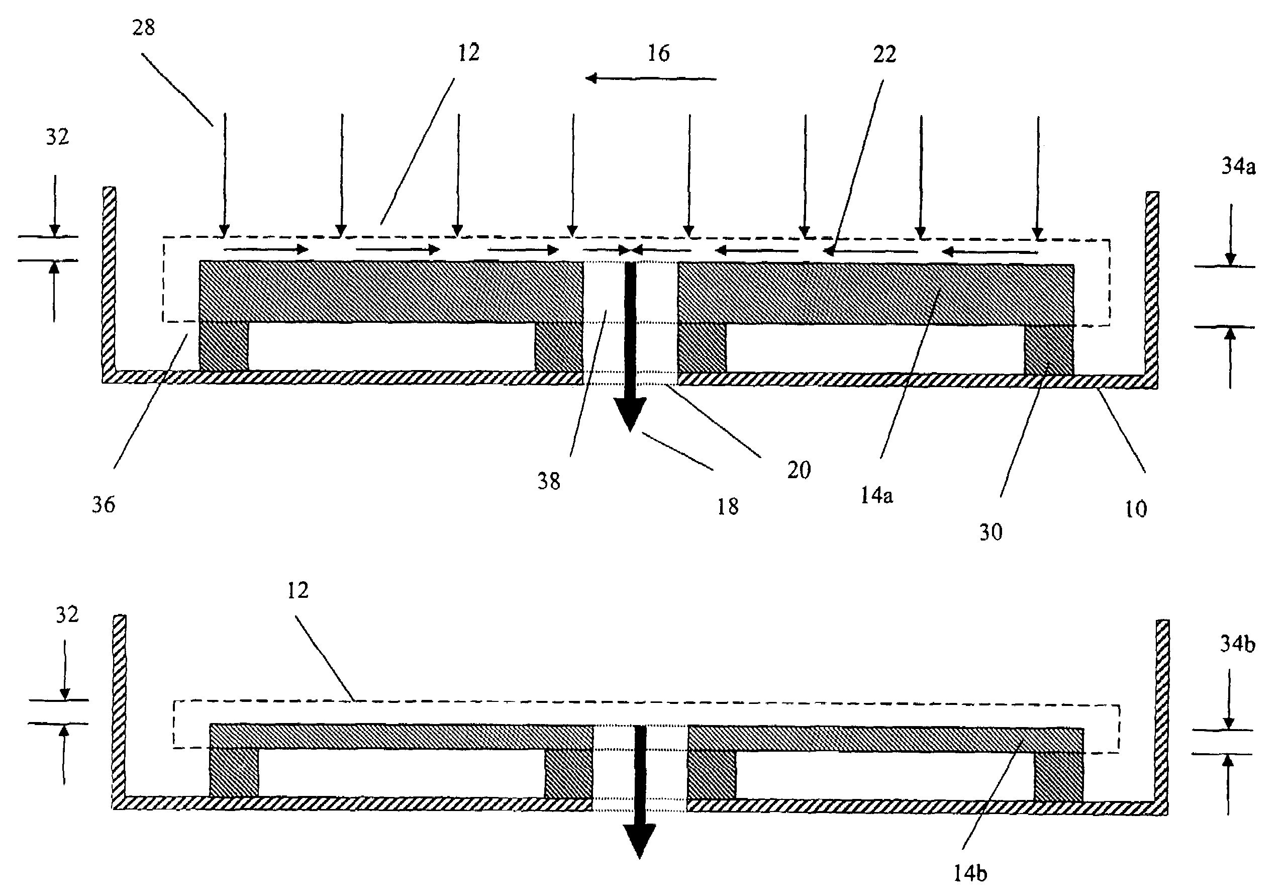
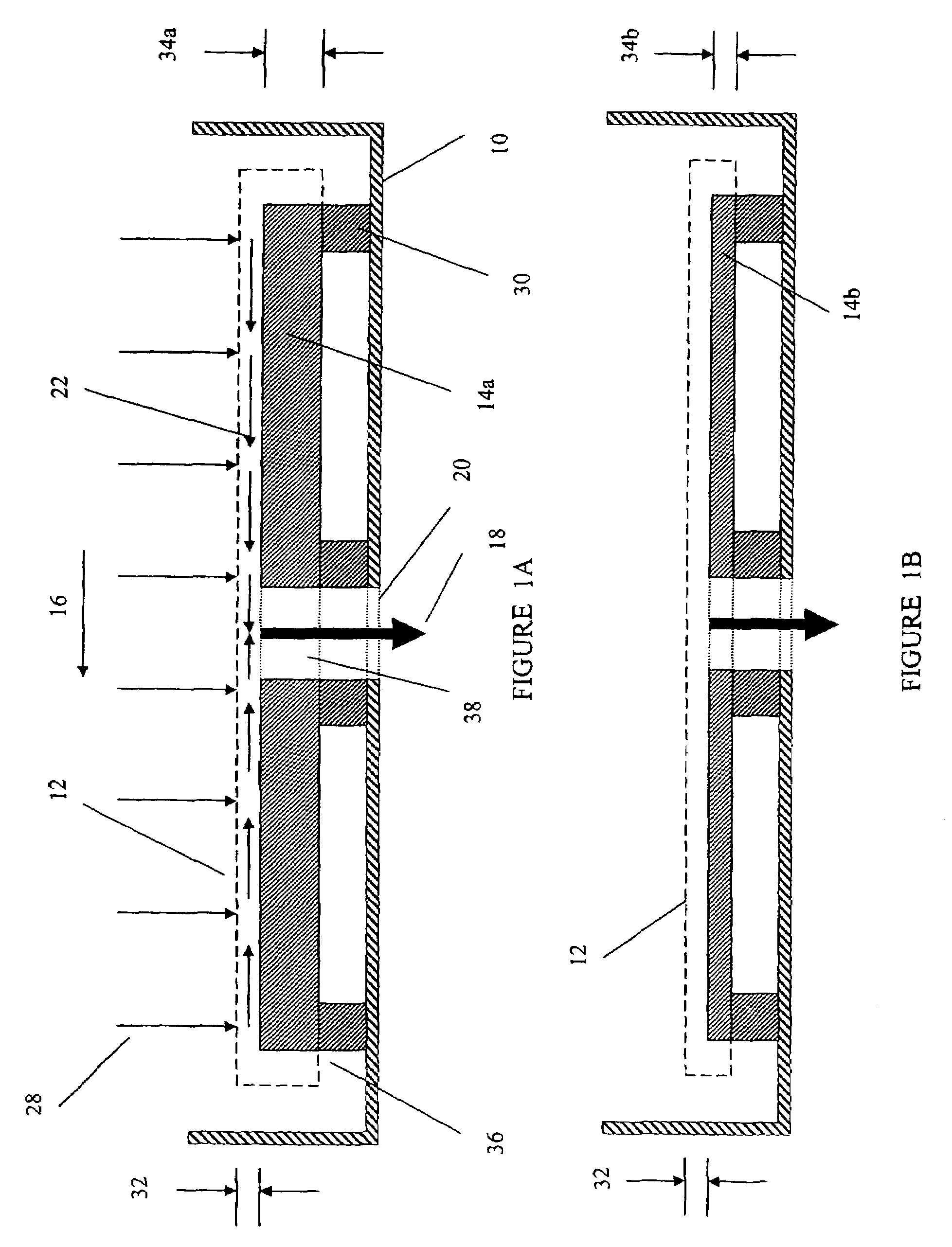
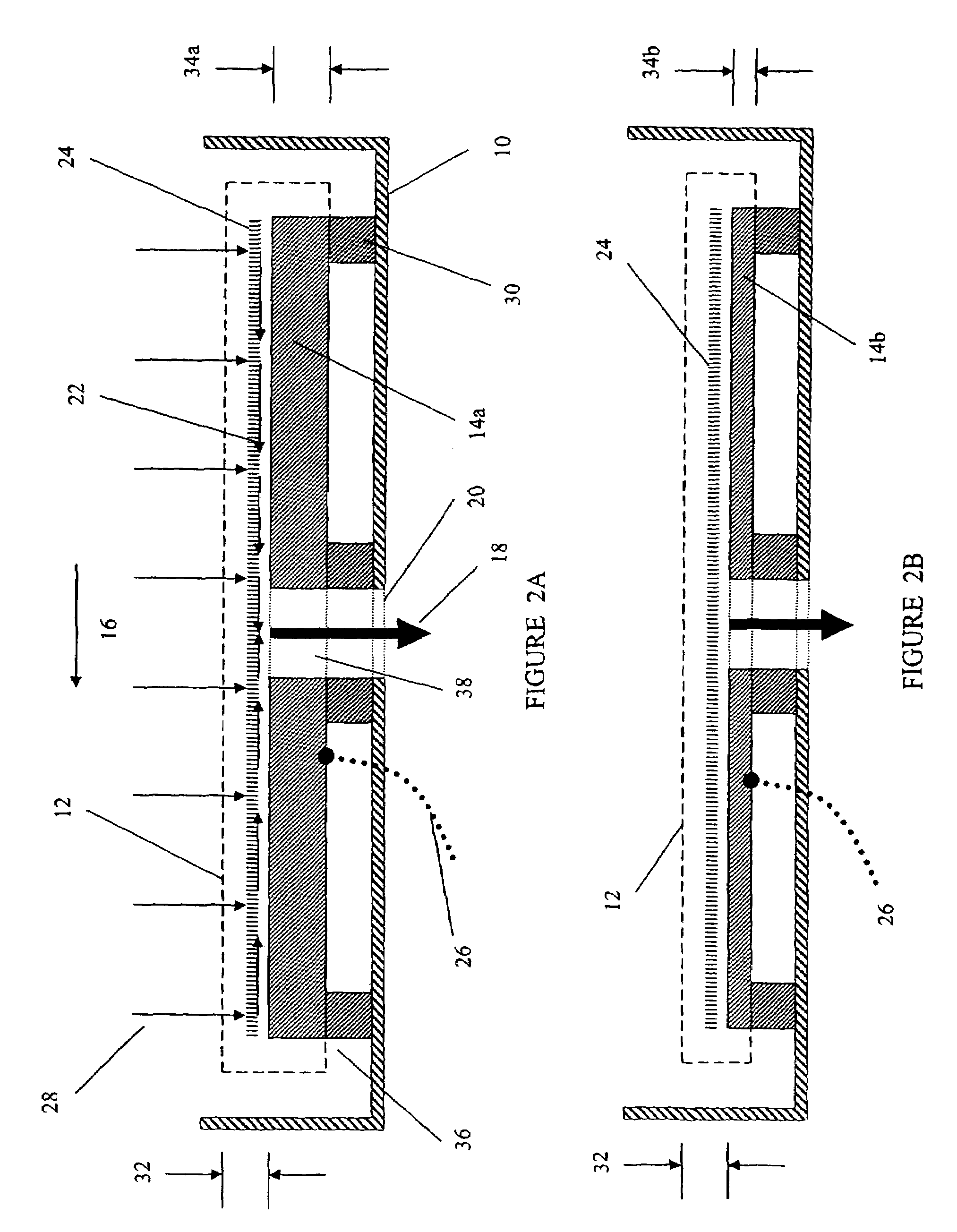
[0058]Control of the boundary layer thickness at a substrate using the present invention is illustrated in FIG. 8A. The thickness of the boundary layer at a substrate, such as the one enclose by a membrane of the present invention may be determined by electrochemical methods. In this example the porous membrane covering the substrate is 0.2 m UPE membrane with a thickness of about 20-40 m. For example it is known that the limiting current in an electrochemical cell is a function of the thickness of the fluid boundary layer at given bulk concentration of ion in the fluid. The limiting current density may be determined through the relationship iL=[(nFDi(surface ion concentration−bulk ion concentration)) / (thickness of boundary layer)]; where n is the charge number for the ion of interest, for example for a cation M+n (i.e. for Cu+2 or Ni2+, n=2), F is the Faraday constant, Di is diffusion coefficient of the ion. The surface ion concentration for M+n may be taken as the concentration of...

example 2

[0061]Mass transfer is a limiting factor in fuel cell efficiency. In order to maximize mass transfer rates the anode-cathode gap is kept small and ion exchange materials are often used in the electrolyte area. The ion exchange membranes have limits in ion transport rates and temperature and are often deteriorated by oxygen.

[0062]A fuel cell with source of fuel 266, source of oxidant 268, and a conforming membrane 276 adjacent to the anode 284 surface could be used to control the fluid boundary layer 282 and maximize mass transfer as shown in FIG. 9. In order to implement the conforming membrane in a fuel cell, electrolyte re-circulation may be established using a pump 280. Re-circulation of the electrolyte would provide electrolyte flow 274 that passes through the membrane 276 and sweeps fluid 282 across the surface of the anode 284. As in other applications a thin under drain layer between the membrane and electrode could be used to improve flow rate and uniformity (not shown). Fur...


PUM

PropertyMeasurementUnit
heightaaaaaaaaaa
heightaaaaaaaaaa
pore sizesaaaaaaaaaa

Abstract

A device and method for increasing the mass transport rate of a chemical or electrochemical process at the solid and fluid interface in a fluid cell. The device includes a membrane in close contact with surface of the work piece, to separate the process cell into two chambers, so that fluid velocity at the work piece is controlled separately from the main cell flow. Thus the diffusion boundary layer is controlled and minimized by the rate that fluid is withdrawn from the work piece chamber.

Description

CROSS REFERENCES TO RELATED APPLICATION[0001]This application claims priority from U.S. Provisional Application Ser. No. 60 / 377,257 filed May 2, 2002, titled “DEVICE AND METHOD FOR INCREASING MASS TRANSPORT AT LIQUID-SOLID DIFFUSION BOUNDARY LAYER”, the contents of which are incorporated herein by reference in their entirety.BACKGROUND OF INVENTION[0002]Many manufacturing processes rely on the chemical or electrochemical reactions at the solid and fluid interface of a flow cell. Examples are electrochemical machining and solid catalysis reactions. Rates of chemical reactions between the fluid and solid interface are governed by the mass transport rate of the reactants or products at the interface. The mass transport rate, determined by Ficks' Law, is proportional to the concentration of the chemical species, the diffusion coefficient and is inversely proportional to the diffusion boundary layer thickness. As the diffusion boundary layer is determined by the fluid velocity near the s...

Claims


Application Information

Patent Timeline
Patent Type & Authority Patents(United States)
IPC IPC(8): C25D17/10B01D61/00B01J4/04B01J19/00B01J19/08B01J19/24C01B3/50C25B15/08C25D5/08C25D17/00C25F7/00F28F13/00F28F13/02H01M2/16H01M8/02H01M8/10
CPCB01D61/00C25D17/008B01J19/2475C01B3/503C25B15/08C25D5/08C25D17/10C25F7/00F28F13/003F28F13/02H01M2/1673H01M8/04201H01M8/1004B01J4/04C01B2203/0405C01B2203/041H01M8/04261Y02E60/521H01M8/04197H01M50/46Y02E60/10Y02E60/50
Inventor WU, QUNWEIBRODEUR, CRAIG L.PILLION, JOHN E.SHYU, JIEH HWA
Owner ENTEGRIS INC
Why Eureka
Try Eureka