
Hall-current ion source for ion beams of low and high energy for technological applications

a technology of ion beams and ion beams, applied in the field of hall-current ion sources, can solve the problems of unrealized regular electron emission and low voltage, and achieve the effects of enhancing gas discharge, high, and enhancing discharg

Inactive Publication Date: 2007-12-25
COLORADO ADVANCED TECH
View PDF14 Cites 13 Cited by
  • Summary
  • Abstract
  • Description
  • Claims
  • Application Information

AI Technical Summary

Benefits of technology

"The present invention introduces an ion source with improved features compared to existing Hall-current type ion sources. The ion source has a broad beam of high current with necessary mean energies, and a filtering schematic to suppress high amplitude discharge current and voltage oscillations at high discharge voltages. The ion source utilizes various ranges of discharge voltages for different technological processes. The invention also introduces a gas distributing system with a placement of working gas holes to reduce discharge pinching and erosion of the gas distribution system. Additionally, the invention provides a safety device to detect ion beam penetration through the reflector, and a method for preventing anode oxidation when the ion source operates close to a target. The invention also allows for easy replacement of the permanent magnet for different discharge voltages and provides a broad beam of high current with necessary mean energies."

Problems solved by technology

These low discharge voltages are under 50 V, which at regular electron emissions are impossible to achieve, because discharge voltages lower than 50 V are not able to maintain gas discharge in an ion source, unless there are utilized quite high pressures in vacuum chamber of about 1-2 and more Millitor.

Method used


Image

  • Hall-current ion source for ion beams of low and high energy for technological applications
  • Hall-current ion source for ion beams of low and high energy for technological applications
  • Hall-current ion source for ion beams of low and high energy for technological applications

Examples


Embodiment Construction

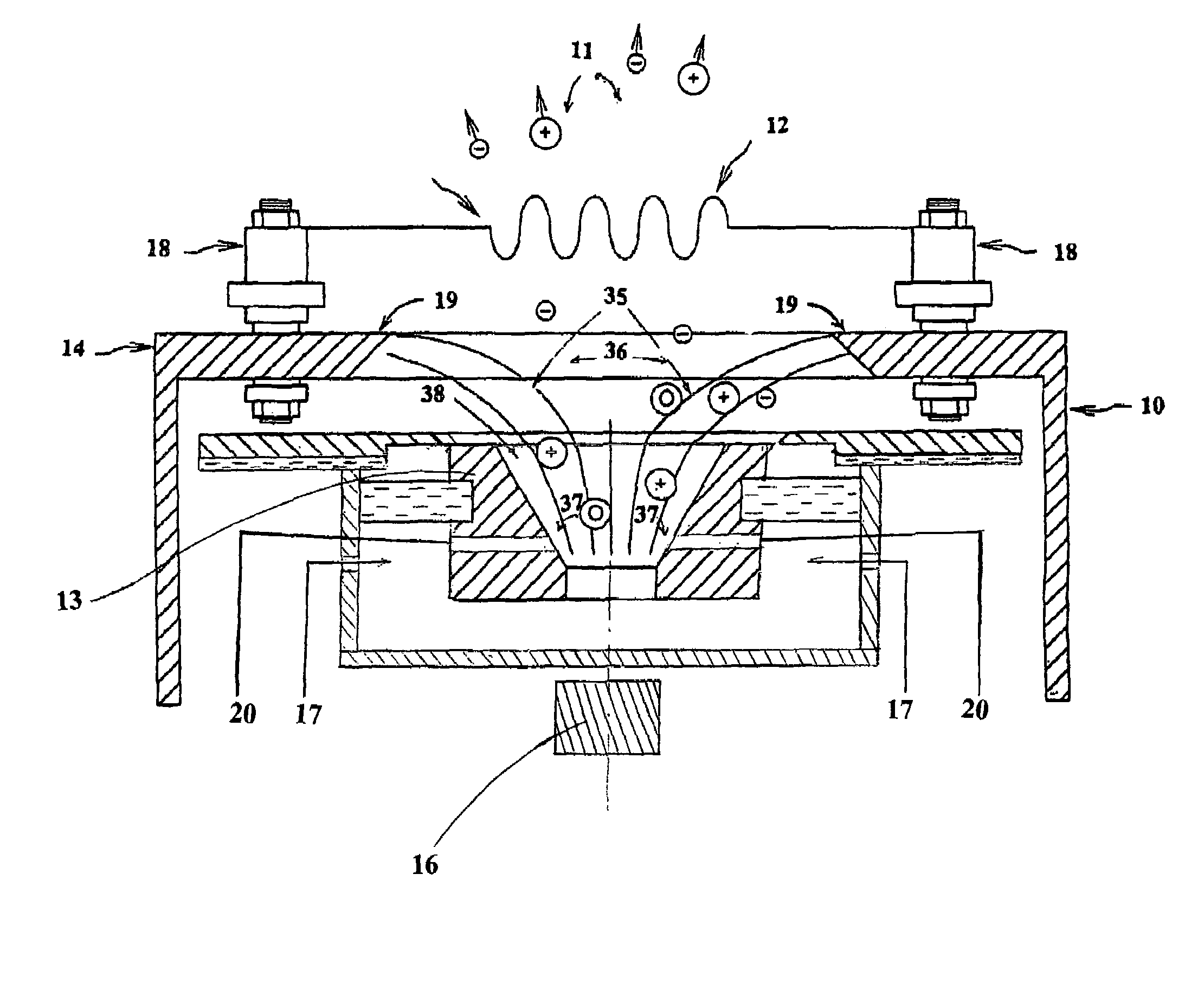
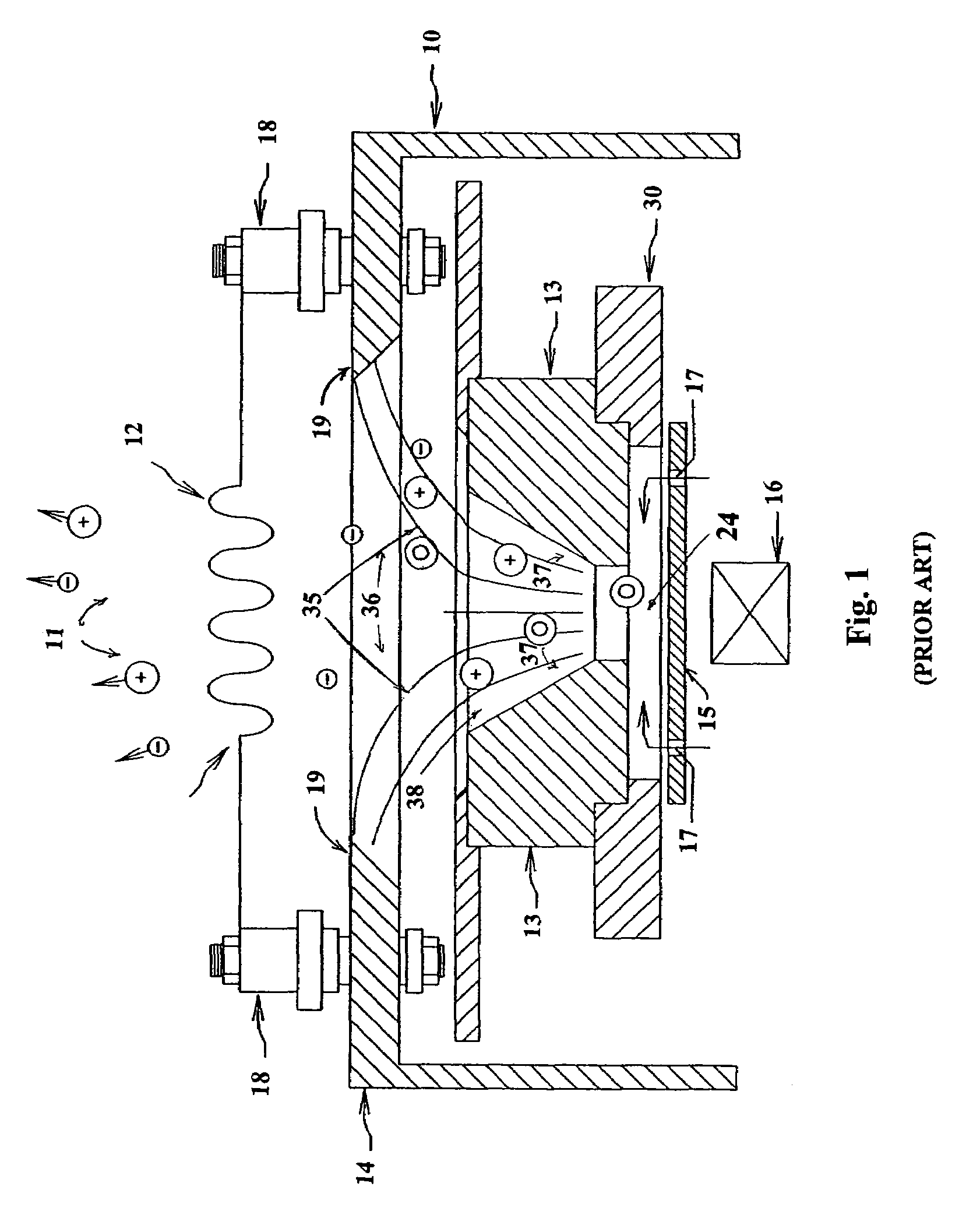
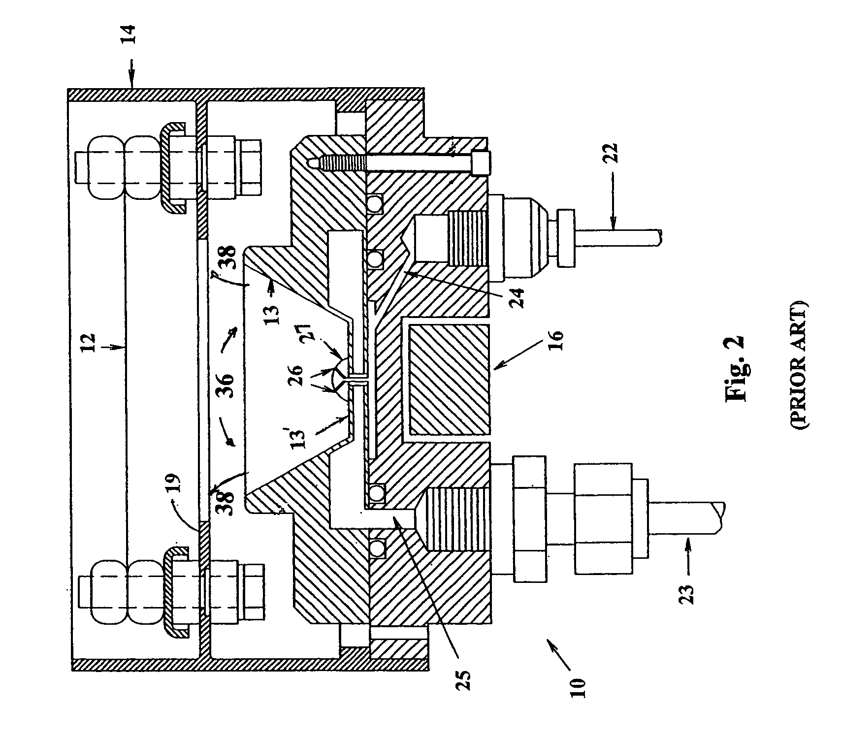
[0041]FIGS. 1 and 2 present schematic drawings of end-Hall ion sources described in U.S. Pat. No. 4,862,032 by Kaufman et al., and in U.S. Pat. No. 6,645,301 B2 by Sainty. Both figures show typical Hall-current ion source apparatus 10 surrounded by a vacuum enclosure (not shown), with vacuum chamber that is maintained at low pressure by a preliminary pumping at about 10−7 torr to 10−4 Torr (typical vacuum conditions of most users of ion sources in thin film technology). End-Hall type ion sources have magnetic field lines 35 that are mostly axial in area of a gas distributing system 24 and radial magnetic field lines in area of an ion source exit 38. An ion source has a magnetic system (shown only an upper part for simplicity) consisting of several parts such as: a magnet 16 representing an internal pole, magnetically permeable shell 14 with an external magnetic pole 19. An ion source 10 produces a plasma flow consisting of ions (on FIG. 1, plus{circle around (+)}sign) accompanied by...


PUM


Abstract

A Hall-current ion source for generation of low and high energy ion beams with selection of magnetic fields and emission currents, where there are utilized low magnetic fields and high emission currents that are higher than discharge currents for low energy ion beams, 15-100 eV; high magnetic fields and emission currents that are equal to discharge currents are utilized for discharge voltages providing ion beam energies of 100-500 eV. Other measures are utilized for protection of a gas distribution area and a magnet from pinching by an ion beam penetration through a reflector by a buffer chamber providing better gas distribution in anode area, a protective ring in a center part of a reflector, and others.

Description

BACKGROUND OF THE INVENTION[0001]1. Field of the Invention[0002]This invention relates in general to the technology of ion and plasma sources, and more particularly to a Hall-current ion source designed for producing broad ion beams of various energies utilized in thin film technology and material processing.[0003]2. Description of the Prior Art[0004]A Hall-current ion source, in some cases also called end-Hall ion source, was described in U.S. Pat. No. 4,862,032 by Kaufman et al. Later it was modified in U.S. Pat. No. 6,608,431 by Kaufman as an ion source of a modular design for easy assembly / disassembly. A very similar concept of a Hall-current ion source was described in a U.S. Pat. No. 6,645,301 by Sainty. Varieties of another Hall-current ion source type called as closed drift ion sources in a form of electric propulsion thrusters and ion sources are known and described by Zhurin et al in article “Physics of Closed Drift Thrusters” in Plasma Sources Science &Technology, Vol. 8 ...

Claims


Application Information

Patent Timeline
Patent Type & Authority Patents(United States)
IPC IPC(8): H01J7/24
CPCH01J27/146H01J2237/08
Inventor ZHURIN, VIACHESLAV V.
Owner COLORADO ADVANCED TECH
Learn More