GMR sensor element and its use

a sensor element and gmr technology, applied in the field can solve the problems of disadvantages of angular sensing accuracy and further offer the possibility of compensating, and achieve the effects of reducing the sensitivity of field direction inhomogeneities and temperature inhomogeneities, reducing the angle sensing accuracy of gmr sensor elements, and reducing the sensitivity to field direction inhomogeneities

Inactive Publication Date: 2007-12-25
ROBERT BOSCH GMBH
View PDF16 Cites 61 Cited by
  • Summary
  • Abstract
  • Description
  • Claims
  • Application Information

AI Technical Summary

Benefits of technology

[0016]By contrast, for an angular sensor that records over 360°, rotational symmetry in the sensor design is a great advantage, so that one does not obtain additional, direction-dependent angular error contributions, just because of an asymmetry in the positioning of the individual GMR resistor elements.
[0017]Therefore, because of the rotationally symmetrical positioning of the GMR resistor elements in the two Wheatstone's bridges, both a reduced sensitivity with respect to field direction inhomogeneities and temperature inhomogeneities is achieved and an undesired AMR signal contribution is suppressed, and, furthermore, the shape anisotropy influence on the pinning behavior and the angle sensing accuracy of the GMR sensor element is reduced. It is also especially advantageous if, besides the rotationally symmetrical positioning of the GMR resistor elements in the two Wheatstone's bridges, an interleaved positioning of the resistors with each other is selected. This leads to a further reduced sensitivity to field direction inhomogeneities and temperature inhomogeneities.
[0019]If the GMR resistor elements have a pinning direction or a reference direction which has been selected to be at least approximately less than 45° to the direction of the strip-shaped structured GMR resistor elements, this leads advantageously to an identical pinning behavior of the individual GMR resistor elements, i.e. especially to an improved signal stability and long-term stability of the GMR sensor element. In this case, the two bridge output signals U1, U2 also have a 45° phase shift with respect to each other.
[0020]Bridge output signals U1, U2, that are phase-shifted by any desired angle ν to each other, ν being preferably 45° or around 45°, may finally, advantageously, be imaged by a coordinate transformation to orthogonal signals having a 90° phase shift. From the latter, the angle α, being sought after, to the direction of outer magnetic field B may be determined, by arctangent formation or a corresponding algorithm, such as the CORDIC algorithm. Beyond this, the coordinate transformation offers the advantage that production-caused fluctuations in the phase difference of the two bridge signals U1, U2 are able to be adjusted during the imaging on the orthogonal signals.

Problems solved by technology

Because, in known GMR angle sensors, the pinning direction or reference direction within a bridge resistor always has a fixed angle to the strip direction, these sensors do not further offer the possibility of compensating for shape anisotropy-conditioned influences on the pinning behavior and such disadvantages on the accuracy of the angular sensing.

Method used


Image

  • GMR sensor element and its use
  • GMR sensor element and its use
  • GMR sensor element and its use

Examples


Embodiment Construction

[0031]a.) Rotationally Symmetrical Positioning

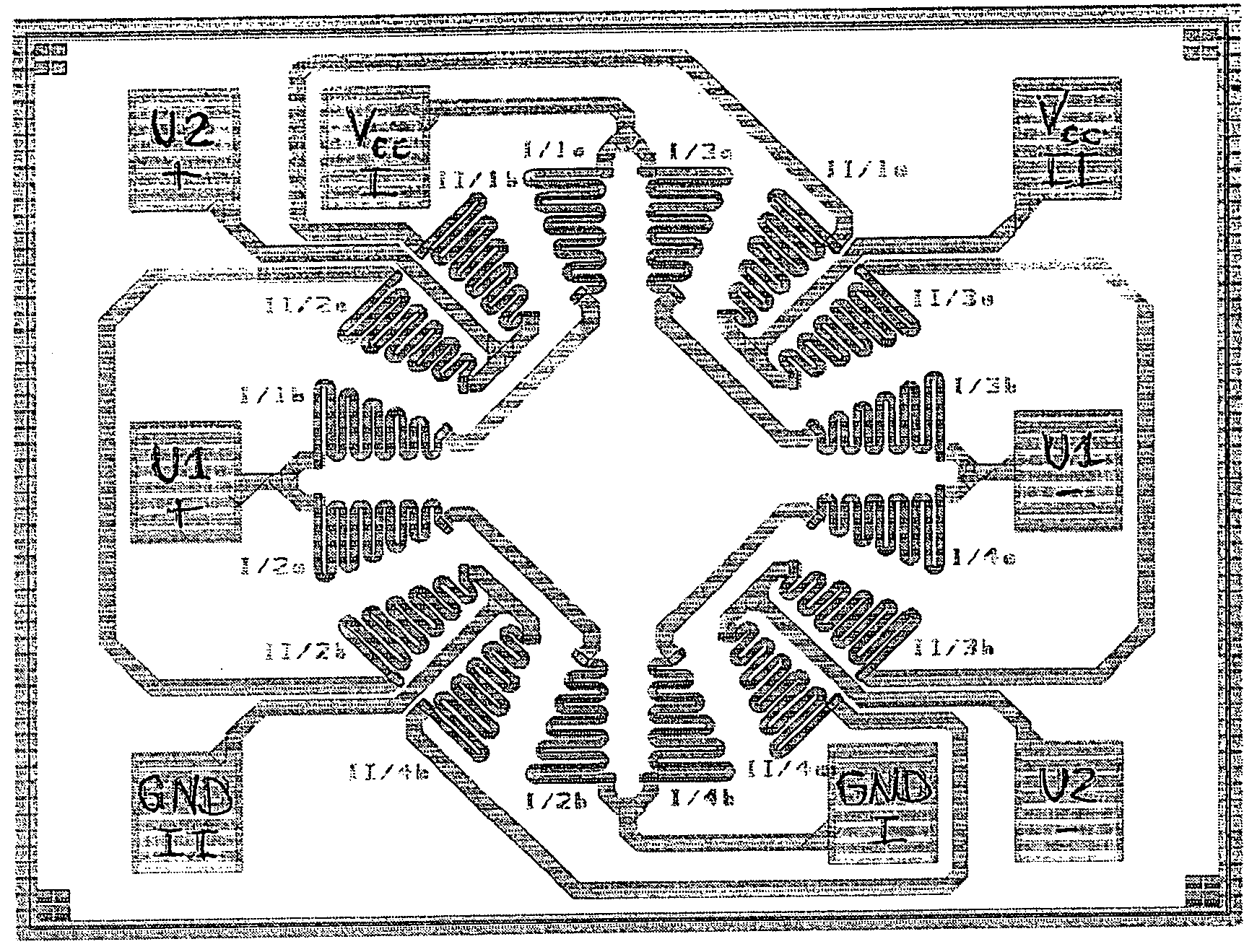
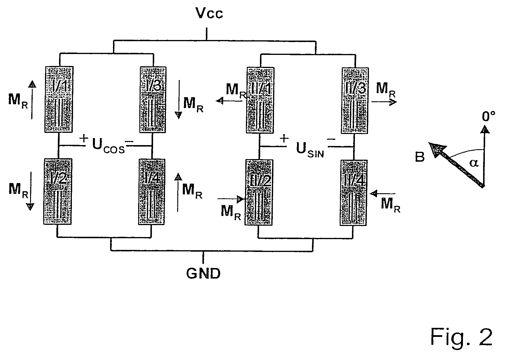
[0032]FIG. 3 shows a possible rotationally symmetrical positioning of altogether eight bridge resistor elements of two full bridges (Wheatstone's bridges). In contrast to AMR sensors, in which the reference direction is given by the current direction which is specified by the strip direction, in the case of the GMR angle sensor, the reference direction is specified by the direction of the magnetization of reference layer (RL). In principle, the pinning direction or reference direction may, in this context, be selected as desired, however, in order to obtain the same pinning behavior for all bridge resistor elements, in this case an orientation of the pinning direction or reference direction is selected that is less than 45° to the strip direction. This is made even clearer in FIG. 4, where, besides the strip direction (strip set inside the resistor symbols) the direction of the reference magnetization MR is also given.

[0033]b.) Imaging o...


PUM


Abstract

A GMR sensor element is proposed, having a rotationally symmetrical positioning of especially eight GMR resistor elements which are connected to each other to form two Wheatstone's full bridges. This GMR sensor element is especially suitable for use in an angle sensor for the detection of the absolute position of the camshaft or the crankshaft in a motor vehicle, particularly in the case of a camshaft-free engine having electrical or electrohydraulic valve timing, of a motor position of an electrically commutated motor, or of detection of a windshield wiper position, or in the steering angle sensor system in motor vehicles.

Description

[0001]This application is a national stage filing under 35 U.S.C. 371 of International Application No. PCT / DE03 / 02145, filed Jun. 27, 2003, which claims priority from German Application No. 102 34 347.0, filed Jul. 26, 2002, and German Application No. 102 57 253.4, filed Dec. 07, 2002, specifications of which are incorporated by reference herein.FIELD OF THE INVENTION[0002]The present invention relates to a GMR sensor element according to the main claim, as well as its use.BACKGROUND INFORMATION[0003]The giant magneto-resistive effect (GMR effect) may be utilized, in the form of so-called spin-valve structures (“spin-valves”) for angular-position sensing. This is described, for example, in PCT International Publication No. WO 00 / 79298 or in European Published Patent Application No. 0 905 523 A2.[0004]GMR spin-valves are made up in essence of two ferromagnetic thin films having a resulting magnetization m1 or m2, which are separated from each other by a nonmagnetic thin film lying in...

Claims


Application Information

Patent Timeline
Patent Type & Authority Patents(United States)
IPC IPC(8): G01R33/09G01B7/30G01R33/02F01L1/00F02D45/00H01L43/08
CPCB82Y25/00F01L1/00G01R33/093F01L2820/041F01L2101/00F01L2301/00
Inventor SCHMOLLNGRUBER, PETERHERRMANN, INGOSIEGLE, HENRIKKITTEL, HARTMUTFARBER, PAULMAY, ULRICH
Owner ROBERT BOSCH GMBH
Why Eureka
Try Eureka