
Hydrodynamic cavitation crystallization device and process

a technology of hydrodynamic cavitation and crystallization device, which is applied in the direction of crystal growth process, separation process, drug composition, etc., can solve the problems of batch crystallization suffering from quality control issues, requiring significant time and money between batches, and allowing adequate quality control

Inactive Publication Date: 2008-01-01
ILLINOIS INSTITUTE OF TECHNOLOGY +1
View PDF8 Cites 31 Cited by
  • Summary
  • Abstract
  • Description
  • Claims
  • Application Information

AI Technical Summary

Benefits of technology

[0091]While the present application illustrates various embodiments, and while these embodiments have been described in some detail, it is not the intention of the applicant to restrict or in any way limit the scope of the claimed invention to such detail. Additional advantages and modifications will readily appear to those skilled in the art. Therefore, the invention, in its broader aspects, is not limited to the specific details, the representative apparatus, and illustrative examples shown and described. Accordingly, departures may be made from such details without departing from the spirit or scope of the applicant's claimed invention.

Problems solved by technology

Batch crystallization equipment and operation is fairly simple but requires a significant investment of both time and money between batches.
Additionally, batch crystallization suffers from quality control issues due to the lack of a steady state during the batch crystallization process.
However, continuous crystallization is normally used for large volume commodity type materials as continuous crystallization does not typically permit adequate quality control to yield crystals suitable for use in industries demanding a high level of crystal size and size distribution control.
However, the direct crystallization of small sized, high surface area particles is usually accomplished in a high supersaturation environment which often results in material of low purity, high friability, and decreased stability due to poor crystal structure formation.
Slow crystallization is a common technique used to increase product purity and produce a more stable crystal structure, but it is a process that decreases crystallizer productivity and produces large, low surface area particles that require subsequent high intensity milling.
However, high energy milling has drawbacks.
Milling may result in yield loss, noise and dusting, as well as unwanted personnel exposure to highly potent pharmaceutical compounds.
Also, stresses generated on crystal surfaces during milling can adversely affect labile compounds.
Overall, the three most desirable end-product goals of high surface area, high chemical purity, and high stability cannot be optimized simultaneously using current crystallization technology without high energy milling.
When using current reverse addition technology for direct small particle crystallization, a concentration gradient can not be avoided during initial crystal formation because the introduction of feed solution to anti-solvent in the stirred vessel does not afford a thorough mixing of the two fluids prior to crystal formation.
The existence of concentration gradients, and therefore a heterogeneous fluid environment at the point of initial crystal formation, impedes optimum crystal structure formation and increases impurity entrainment.
Another standard crystallization procedure employs temperature variation of a solution of the material to be crystallized in order to bring the solution to its supersaturation point, but this is a slow process that produces large crystals.
Also, despite the elimination of a solvent gradient with this procedure, the resulting crystal characteristics of size, purity and stability are difficult to control and are inconsistent from batch to batch.

Method used


Image

  • Hydrodynamic cavitation crystallization device and process
  • Hydrodynamic cavitation crystallization device and process
  • Hydrodynamic cavitation crystallization device and process

Examples


example 1

[0072]Three p-acteylaminophenol (acetaminophen) solutions are prepared as follows: 23.888 grams of p-acteylaminophenol is added to 100 grams of 30:70 by weight water / EtOH solution. The crystallization process is carried out in the device of FIG. 12 where F1, F3, and F4 are anti-solvent fluid streams and F2 is a feed solution. The anti-solvent is water and is added via F1, F3, and F4 to yield a final volume ratio of anti-solvent to feed solution of 70:30 when mixed fluid stream Fm exits the nucleating section of device 1200. No additional heating, cooling or pH modification is conducted in intermediate section 802.

[0073]In the crystal growth section 900 of device 1200, mixed fluid stream Fm is re-circulated via a high pressure pump through a hydrodynamic cavitation crystallization sub-section 910 containing cavitation generator 920.

[0074]The pressure of pump 906 is varied according to Table 1 and the re-circulation time is held constant at 5 minutes. At the end of the re-circulation ...

example 2

[0076]Two p-acteylaminophenol (acetaminophen) solutions are prepared as follows: 23.888 grams of p-acteylaminophenol is added to 100 grams of 30:70 by weight water / EtOH solution. The crystallization process is carried out in the device of FIG. 12 where F1, F3, and F4 are anti-solvent fluid streams and F2 is a feed solution. The anti-solvent is water and is added via F1, F3, and F4 to yield a final volume ratio of anti-solvent to feed solution of 70:30 when mixed fluid stream Fm exits the nucleating section of device 1200. No additional heating, cooling or pH modification is conducted in intermediate section 802.

[0077]In the crystal growth section 900 of device 1200, mixed fluid stream Fm is re-circulated via a high pressure pump through a hydrodynamic cavitation crystallization sub-section 910 containing cavitation generator 920.

[0078]The pressure of pump 906 is varied according to Table 2 and the re-circulation time is held constant at 15 minutes. At the end of the re-circulation t...

example 3

[0080]Two p-acteylaminophenol (acetaminophen) solutions are prepared as follows: 23.888 grams of p-acteylaminophenol is added to 100 grams of 30:70 by weight water / EtOH solution. The crystallization process is carried out in the device of FIG. 12 where F1, F3, and F4 are anti-solvent fluid streams and F2 is a feed solution. The anti-solvent is water and is added via F1, F3, and F4 to yield a final volume ratio of anti-solvent to feed solution of 70:30 when mixed fluid stream Fm exits the nucleating section of device 1200. No additional heating, cooling or pH modification is conducted in intermediate section 802.

[0081]In the crystal growth section 900 of device 1200, mixed fluid stream Fm is re-circulated via a high pressure pump through a hydrodynamic cavitation crystallization sub-section 910 containing cavitation generator 920.

[0082]The pressure of pump 906 is varied according to Table 3 and the re-circulation time is held constant at 30 minutes. At the end of the re-circulation t...


PUM

PropertyMeasurementUnit
weightaaaaaaaaaa
pressureaaaaaaaaaa
weightaaaaaaaaaa

Abstract

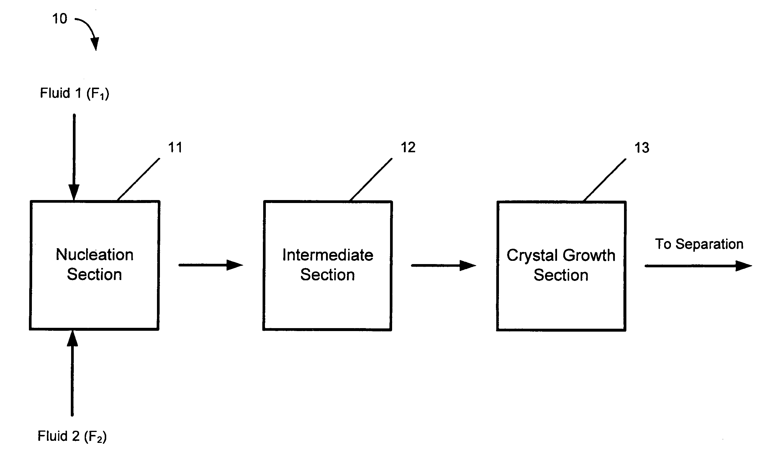
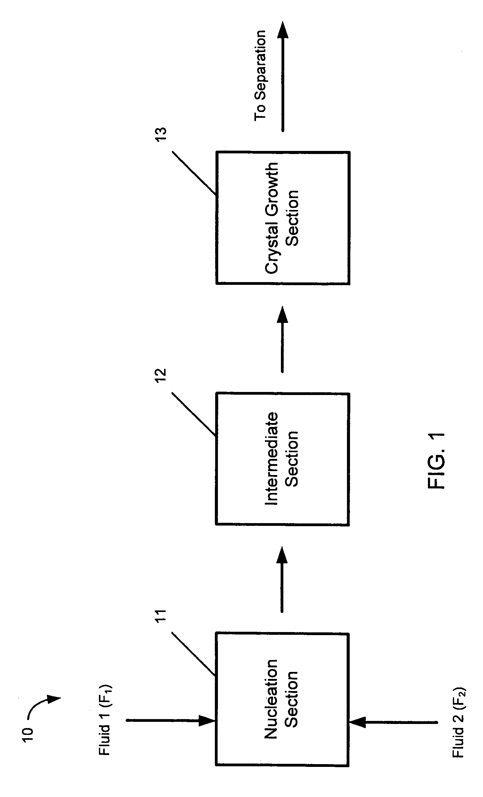
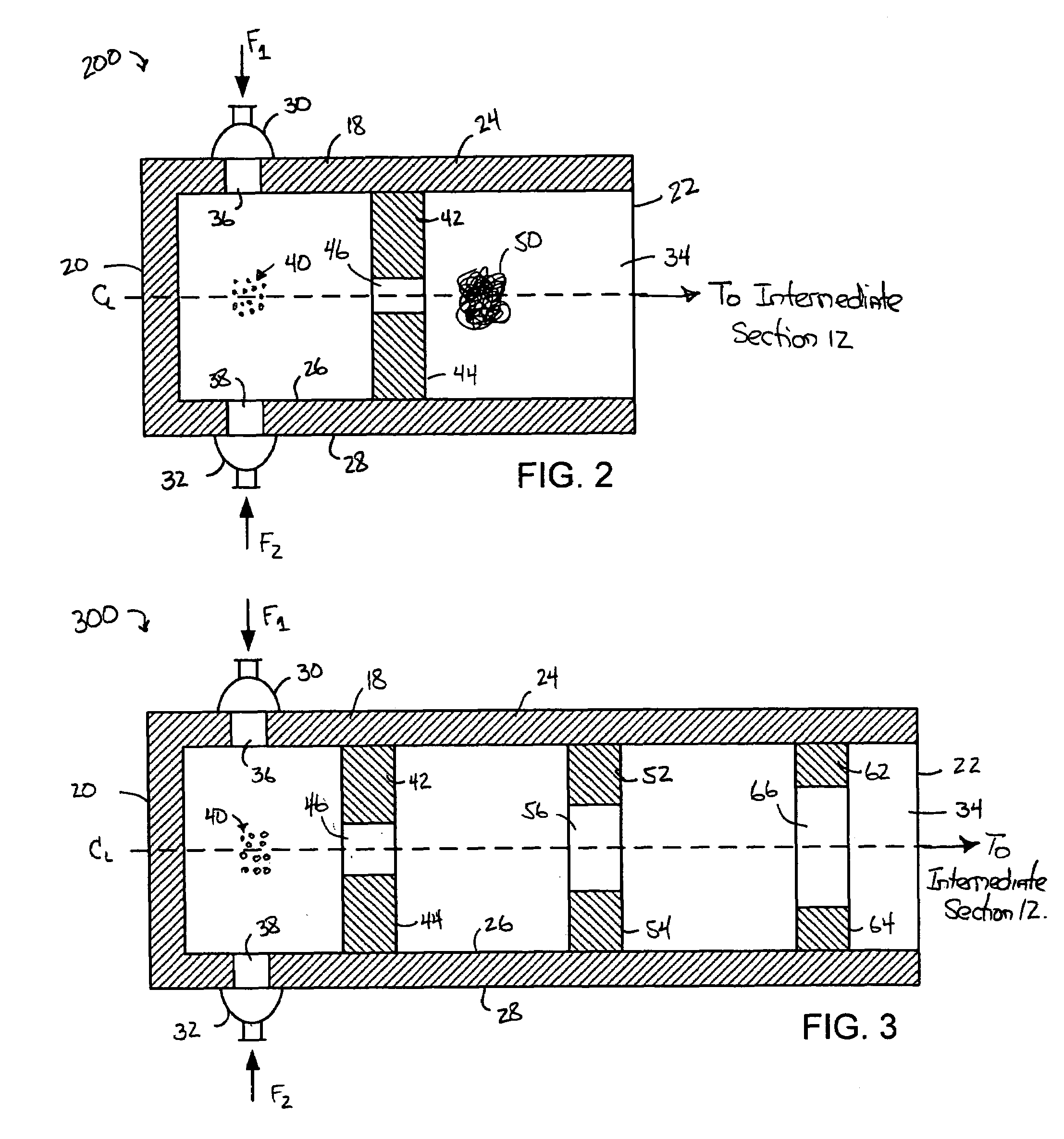
A device and process for crystallizing a compound using hydrodynamic cavitation comprising the steps of mixing at least one stream of a feed solution of such compound to be crystallized with at least one stream of an anti-solvent in a nucleating section via collision of the feed solution and the anti-solvent, passing the mixed streams at an elevated pressure through at least one local constriction of flow to create hydrodynamic cavitation thereby causing nucleation and the production of seed crystals, passing the fluid stream containing the seed crystals through an intermediate section to a crystal growth section, passing the fluid stream containing the seed crystals through the crystal growth section at an elevated pressure through at least one local constriction of flow to create hydrodynamic cavitation thereby causing further crystallization of the compound contained in the solution.

Description

BACKGROUND OF THE INVENTION[0001]The present invention relates to a device and process for crystallizing compounds using hydrodynamic cavitation. The types of compounds that may be crystallized include pharmaceutical compounds, chemical compounds, food additive compounds, as well as any other compounds used in industry.[0002]Crystallization from solution is a separation and purification method used in the chemical, food and pharmaceutically industries, particularly for the production of active compounds or their intermediates. Some of the goals of the crystallization process include producing a product meeting the desired purity level and also a product having the desired crystal size and size distribution. Crystallization from solution is usually conducted as a batch process or as a continuous process. Batch crystallization equipment and operation is fairly simple but requires a significant investment of both time and money between batches. Additionally, batch crystallization suffe...

Claims


Application Information

Patent Timeline
Patent Type & Authority Patents(United States)
IPC IPC(8): C30B29/58
CPCC30B29/54C30B7/00A61P29/00C30B7/02C30B7/14C30B7/04C30B7/06
Inventor KOZYUK, OLEG V.MYERSON, ALLAN S.WEINBERG, ROGER
Owner ILLINOIS INSTITUTE OF TECHNOLOGY
Learn More