However, as a matter of practice, in the absence of such ideal switches, conventional
single stage converter implementations do not function in AC to AC conversions.
Simple power transformers are in common usage, though necessarily restricted to
AC power conversion; however, they grow heavy and bulky as power levels increase, and they are by nature not readily variable in their conversion ratios without some kind of tap changing modification.
There has been some work done in the area of AC
converters, but known methods suffer for one or more reasons.
For instance, some employ simplistic control schemes that lead to a variety of failure
modes in the switches.
In all real world switches, there exist timing delays and finite rise / fall times, both of which vary from
device to device and over varying operating conditions.
If care is not taken in a conventional two switch converter as outlined above, both switches could conduct simultaneously, with attendant high currents and excessive power dissipation which can destroy the switches.
Power transistors of some of the types commonly employed as switches in converter topologies (and other semiconductors similarly employed) are known to store significant amounts of charge, and if a control voltage is applied to turn one
transistor off as the control voltage is being applied to turn the other
transistor on, the flow of current in the first
transistor would continue for sometime after the turn off control, and simultaneous conduction in both transistors would occur to cause a short across the power source, with potentially damaging current flow through the switches.
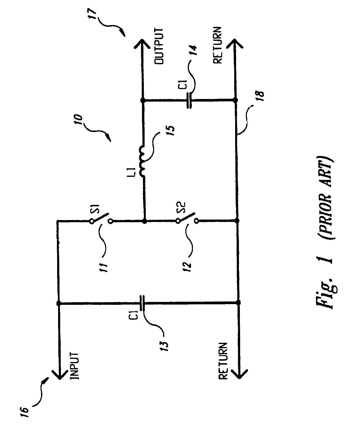
A simultaneous “off” condition for both transistors is also a problem, for if the first transistor is turned off before the second transistor is turned on, the series
inductor in such regulating circuits (in series with the opening switch) would
discharge through the opening switch and subject the switch to potentially damaging voltage.
In the
AC circuit supposed above, however, that then results in both switches being disabled at the same time.
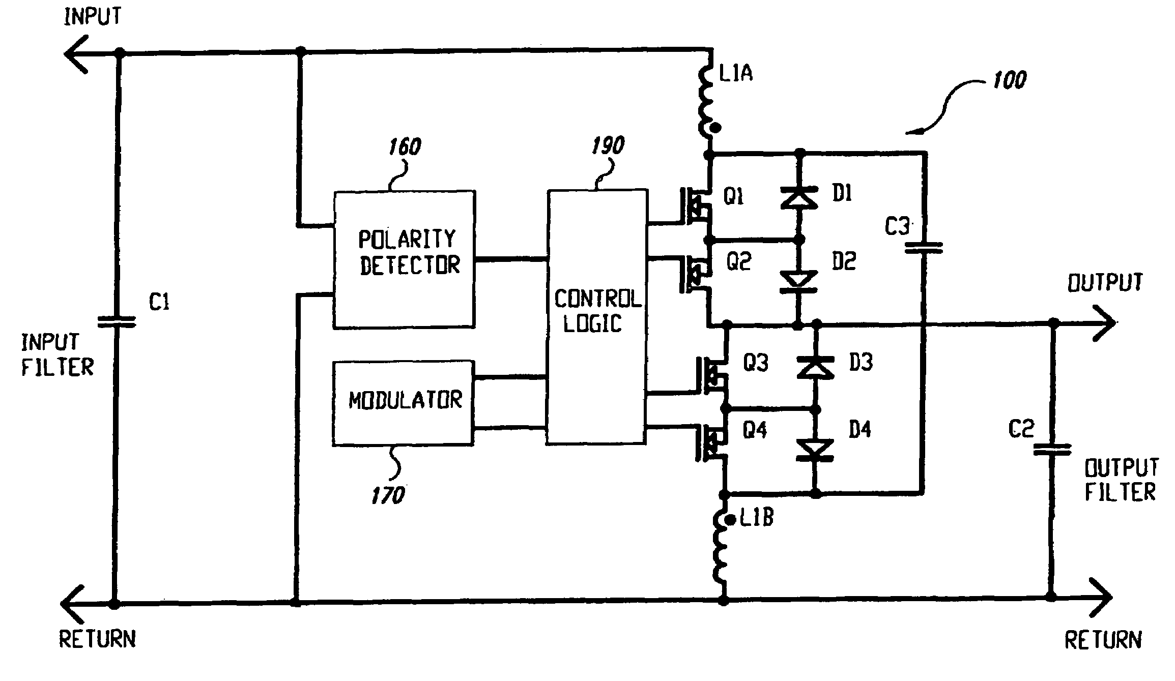
Also as discussed above, if any current is flowing in the output
inductor L1, then the result of both switches simultaneously disabled is a
voltage spike across the switches which will likely destroy them.
This spike typically has to be clamped via some
snubber or clamping network, but that may result in excessive clamp power dissipation and excessive switching losses in the switches.
Converters employing these techniques tend to be more efficient in theory than the “hard” switching circuits using snubbers mentioned above, but some topologies have proven difficult to control, where the resonant circuit becomes increasingly unstable at lower power ranges.
In addition, such resonant circuits also have more narrowly defined operating conditions (i.e., minimum and maximum current limitations), and are therefore less robust for industrial applications, and these circuits typically trade switch losses for increased conduction losses, and require bulky resonant componentry.
As a result, there is always a significant switch or
snubber dissipation.
In addition, during
high current surge conditions, the
snubber may not be able to adequately limit the voltage rise, leading to potentially catastrophic
device failure.
These known circuits therefore have significant limits in capability of conversion, at least in terms of output power, efficiency, reliability and cost.
This is especially the case with present high power
semiconductor technology where
higher power and lower cost devices are also generally the slowest, and therefore have inherent and unacceptably high switching losses.
These suggested control schemes have a number of points in common: 1) they all have multiple switches operating simultaneously at high frequencies; 2) the timing between these switches is highly critical, in order to avoid cross conduction or voltage spikes from the output inductor; 3) maximum
duty cycle may have to be limited to accommodate what may be required as fixed timing delays, and circuit
response time to output overload can be consequently dangerously delayed; 4) they all apply high frequencies voltage waveforms to the output inductor, which frequencies are essentially the same from no load to full load and which results in a fixed core loss in the inductor with attendant significant
power loss even at
light load or no load operation, thus reducing conversion efficiency at
light load with attendant increased
electricity costs; 5) by employing an unchanging
high frequency waveform, the
switching frequency AC current component in the output inductor is also similar from no load to full load condition, so that at
light load significant current is left circulating through power components like transistors, diodes, and filter capacitors, all with attendant significant
power loss and reduced light load conversion efficiency and increased
electricity costs; and 6) they all modulate multiple switches at high frequencies, which leads to high
average current requirements for control circuitry, especially with large
semiconductor power devices like IGBT's,
MOSFET's, BJT's and MCT's.
A major
disadvantage of this conventional PFC technique is that the output switches always switch to and from the DC storage
bank voltage, which is above the peak power line voltage.
As a result, switching losses are quite high.
Known automatic
power factor correctors are bulky, slow and complex, and therefore only practical for large motors and groups of smaller motors.
For the above reasons, and other as will be appreciated by those skilled in the art, it is not practical to connect conventional PFC equipment at each load (motor).
These non-linear devices typically only draw current when the voltage is at its peak, thus causing the
harmonic distortion.
This is not how the
power grid was designed to work.
This is already even true for conventional PFC techniques that, in addition to other noted disadvantages, also react themselves to exacerbate
harmonic problems, amplify circuit resonances, and even cause “
ringing” on the mains when capacitors are switched.
It has been suggested that the variety of
power quality problems, now extant and steadily growing in magnitude and variety, are all actually summed within a power
distribution system, producing effects such as: deterioration of
electronic equipment performance, and continuous or sporadic computer and other
microprocessor malfunctions;
tripping protection circuitry of adjustable speed drives; overheating of neutral in
three phase systems, leading to neutral
burnout; overheating and
premature failure of transformers, even when the
transformer rating appears otherwise adequate; overheating of motors; nuisance
tripping of circuit breakers; telephone interference; and PFC
capacitor fuse blowing.
This scheme is relatively simple to implement, but is electrically very noisy, which leads to additional design problems and additional implementation costs.

