
Compact distillates fuel processor with effective sulfur removal process

a distillate fuel and process technology, applied in the field of reformers, can solve the problems of difficult storage and transportation, low efficiency, and low efficiency of hydrogen gas, and achieve the effect of high efficiency

Inactive Publication Date: 2008-01-15
APPLIED RES ASSOCS INC
View PDF37 Cites 14 Cited by
  • Summary
  • Abstract
  • Description
  • Claims
  • Application Information

AI Technical Summary

Benefits of technology

[0013]The present invention has been made in light of the aforementioned problems associated with steam reforming of distillate fuels. A broad object of the present invention is to provide a novel method and apparatus for steam reforming of liquid distillate fuels with high overall process thermal efficiency and compact overall dimensions.
[0014]A more specific object of the present invention is to provide for steam reforming of distillate fuels in as compact an apparatus as possible by minimizing the amount of sulfur and aromatic hydrocarbon directed to desulfurization and reforming operations, and by using microchannel heat exchangers and reactors assembled in slab configurations.

Problems solved by technology

Hydrogen gas is not a widely distributed fuel, and is difficult to store and transport.
Alcohol fuels, such as methanol and ethanol, can be readily reformed to hydrogen gas, but are also not widely available.
While distillate fuels are more widely distributed than alcohol fuels or natural gas, they also present some unique complications in steam reforming processes.
Specifically, coke formation and sulfur poisoning are two common problems in steam reforming of distillate fuels.
Coking of the reforming catalyst surface may result from imperfect mixing of fuel vapor and steam at the reforming reactor inlet.
Imperfect mixing leads to gradients in temperature and steam / carbon ratio over the catalyst surface, with coke formation occurring in those regions where temperature or steam / carbon ratios are low.
Coke formation initially causes lowered catalyst activity, and ultimately can lead to plugging of the reforming reactor.
Increasing the steam / carbon ratio of the steam / fuel mixture can diminish coking; however, this results in wasted steam and lower overall process efficiency.
Hydrogen sulfide is readily adsorbed, while alkyl sulfides are more difficult to remove, thiophenes more difficult still, and substituted benzothiophenes are highly stable and only weakly adsorbed.
Direct desulfurization of the liquid distillate fuel feed to acceptable sulfur concentrations using conventional adsorbents may therefore require impractically large adsorbent beds.
However, indiscriminate combustion of the fuel feed is thermally inefficient, because hydrogen-rich aliphatic species in the feed are combusted along with hydrogen-poor aromatic species.
Gas / liquid separation is not used to separate light hydrocarbons from uncracked residue downstream from the cracking reactor, making the Shimazu process unsuitable for use with middle distillate fuels such as diesel, kerosene or JP-8 which contain significant amounts of higher molecular weight aromatic species.

Method used


Image

  • Compact distillates fuel processor with effective sulfur removal process
  • Compact distillates fuel processor with effective sulfur removal process
  • Compact distillates fuel processor with effective sulfur removal process

Examples


first embodiment

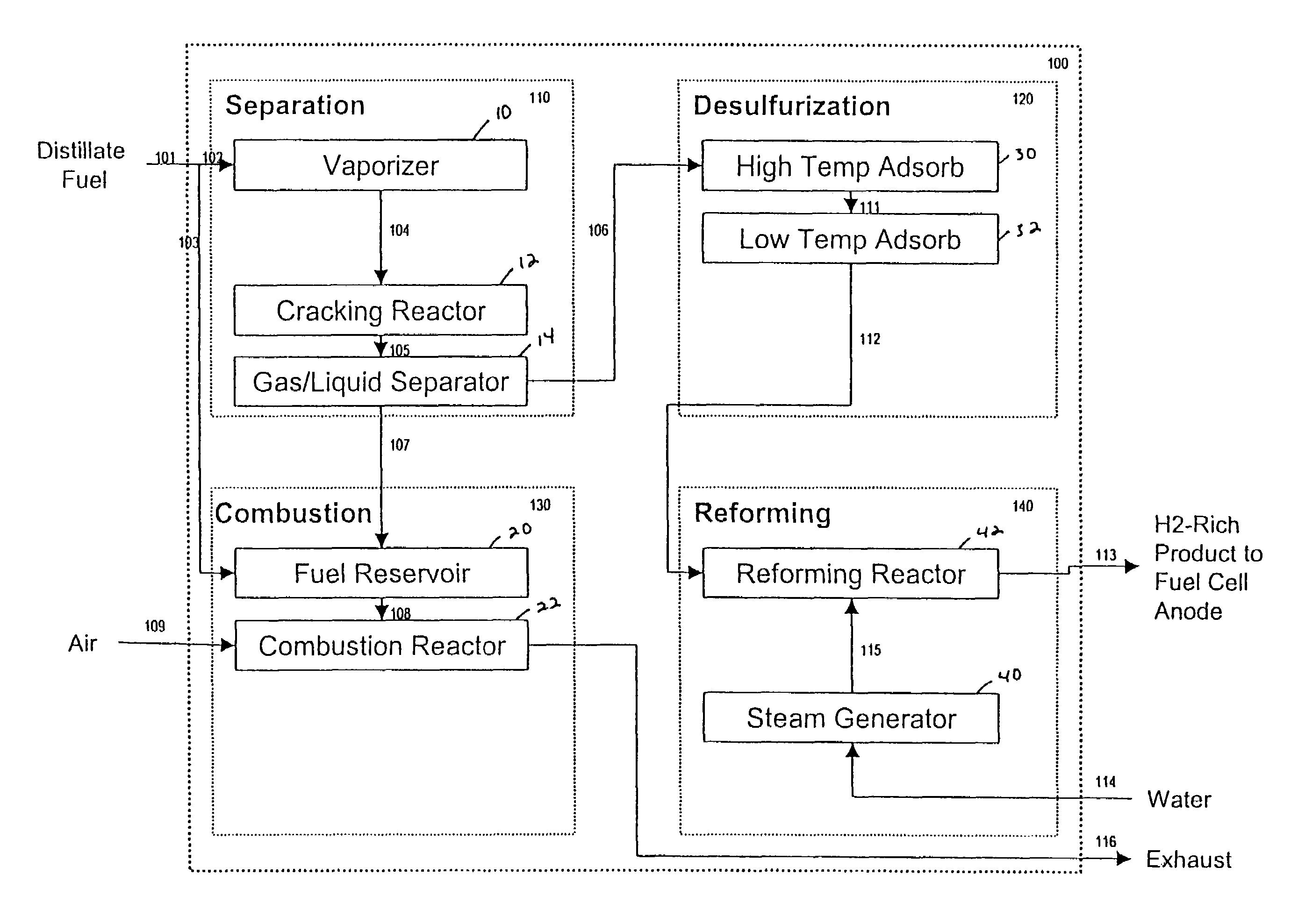
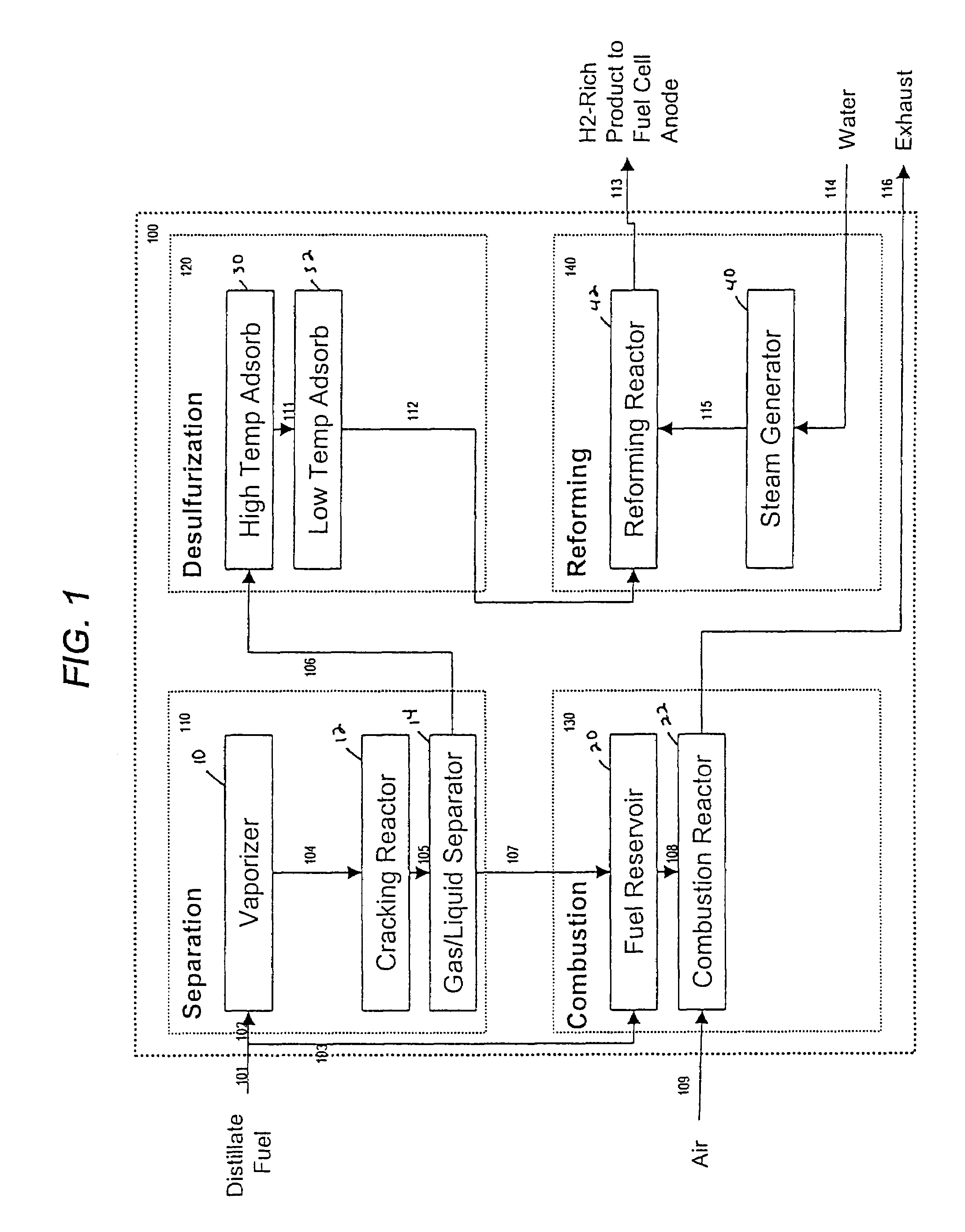
[0040]the present invention, a schematic process flow diagram of which is shown in FIG. 1, is an apparatus 100 comprising four distinct assemblies, namely a separation assembly 110, a desulfurization assembly 120, a combustion assembly 130, and a reforming assembly 140. In this embodiment, the separation assembly 110 includes a fuel vaporizer 10, a catalytic cracking reactor 12 and a gas / liquid separator 14.

[0041]A distillate fuel feed stream 101 is split into a vaporizer feed stream 102, and a combustion fuel makeup stream 103. A vaporized and superheated fuel stream 104 is directed from the vaporizer 10 to the catalytic cracking reactor 12 in which the aliphatic content of the fuel is selectively cracked to light hydrocarbon gases while, at the same time, any sulfur present in the fuel as organosulfur species is converted to hydrogen sulfide. The aromatic content of the fuel remains largely unconverted. The catalyst contained in the catalytic cracking reactor 12 is chosen to provi...

fourth embodiment

[0061]the invention, as depicted in FIG. 4, shows a system with water recovery components within the combustion assembly 430 and the reforming assembly 440, such that no water feed stream to the reforming apparatus 400 is necessary. Because water is produced in the combustion reactor component of the combustion assembly 430 and in the fuel cell cathode reaction, the water requirements of the reforming process can be balanced by 68% water recovery in these two water recovery components.

[0062]Two approaches can be applied to achieve this water recovery. One uses condensation by cooling the exhaust stream to near ambient temperature, while the other operates by expanding the humid air to atmospheric pressure in a turbine. In both cases the fuel cell stack will operate at elevated pressure and temperature and a water-air separation is applied. In the turbine application, a compressor can be installed on the turbine shaft, to provide fuel cell stack with pressurized air. The expansion en...


PUM

PropertyMeasurementUnit
Temperatureaaaaaaaaaa
Percent by massaaaaaaaaaa

Abstract

A distillate fuel steam reformer system in which a fuel feed stream is first separated into two process streams: an aliphatics-rich, sulfur-depleted gas stream, and an aromatics- and sulfur-rich liquid residue stream. The aliphatics-rich gas stream is desulfurized, mixed with steam, and converted in a reforming reactor to a hydrogen-rich product stream. The aromatics-rich residue stream is mixed with air and combusted to provide heat necessary for endothermic process operations. Reducing the amounts of sulfur and aromatic hydrocarbons directed to desulfurzation and reforming operations minimizes the size and weight of the overall apparatus. The process of the invention is well suited to the use of microchannel apparatuses for heat exchangers, reactors, and other system components, which may be assembled in slab configuration, further reducing system size and weight.

Description

[0001]This is a complete utility application entitled to the priority and claiming the benefit of U.S. provisional application Ser. No. 60 / 394,661 filed Jul. 10, 2002, which is hereby incorporated by reference in its entirety.TECHNICAL FIELD OF THE INVENTION[0002]The present invention relates to a reformer for reforming hydrocarbon distillate fuels such as gasoline, diesel fuel, jet fuels such as Jet A and JP-8, kerosene, and the like, to produce hydrogen as a, fuel for use in fuel cells. More particularly, the present invention relates to an improvement in a steam reformer for integration of fuel feedstock pretreatment operations and reformer system thermal management.BACKGROUND OF THE INVENTION[0003]Fuel cells are able to convert hydrogen fuel to electric power in a simple, efficient process with low pollutant emissions, and are therefore of considerable commercial interest. A number of fuel cell designs have been introduced, using various operating temperatures. Both low temperat...

Claims


Application Information

Patent Timeline
IPC IPC(8): B01J7/00B01J8/00C10G45/00C01B3/38C10G55/06C10G57/00
CPCC01B3/38C10G55/06C10G57/00C01B2203/0233C01B2203/0811C01B2203/0827C01B2203/1247C01B2203/1258C01B2203/127
Inventor SHAABAN, ALY H.CAMPBELL, TIMOTHY J.
Owner APPLIED RES ASSOCS INC
Learn More