Image sensor device and manufacturing method thereof

a technology of image sensor and manufacturing method, which is applied in the direction of solid-state devices, radio-controlled devices, transistors, etc., can solve the problems of insufficient ability, dark current, and excessive dark current, and achieve the effect of reducing the occurrence of dark curren

Active Publication Date: 2008-01-22
MARLIN SEMICON LTD
View PDF13 Cites 6 Cited by
  • Summary
  • Abstract
  • Description
  • Claims
  • Application Information

AI Technical Summary

Benefits of technology

[0009]Therefore the present invention provides an image sensor and a manufacturing method thereof to effectively protect the surface of the image sensor and to reduce dark current.
[0012]Because the STI and the LOCOS layer are formed separately, and the STI is used to electrically isolate the active areas from each other while the LOCOS layer is used to be a protection layer for the photodiode and the gate insulator of the gate, the present invention provides an image sensor having lower occurrence of dark current without influencing the demand for the integration. Moreover, because the gate insulator has different thickness in accordance with the claimed invention, a mechanism which effectively turns off the gate is provided to further reduce the occurrence of dark current.

Problems solved by technology

Excessive dark current lowers the dynamic range of the CMOS image sensor because there is insufficient ability to distinguish between the light and dark currents.
Generally, dark current is related to surface defects, plasma damage, and wafer impurity, etc., which result from the manufacturing process.
For example, after forming the photodiode of a CMOS image sensor, the surface of the photodiode tends to be damaged during the plasma etching process, and thus dark current occurs.
However, the LOCOS layer formed by a LOCOS process consumes a larger surface, and occupies valuable space on a wafer when being used to isolate the photodiode from other device, which therefore reduces integration and increases cost.

Method used


Image

  • Image sensor device and manufacturing method thereof
  • Image sensor device and manufacturing method thereof
  • Image sensor device and manufacturing method thereof

Examples


Embodiment Construction

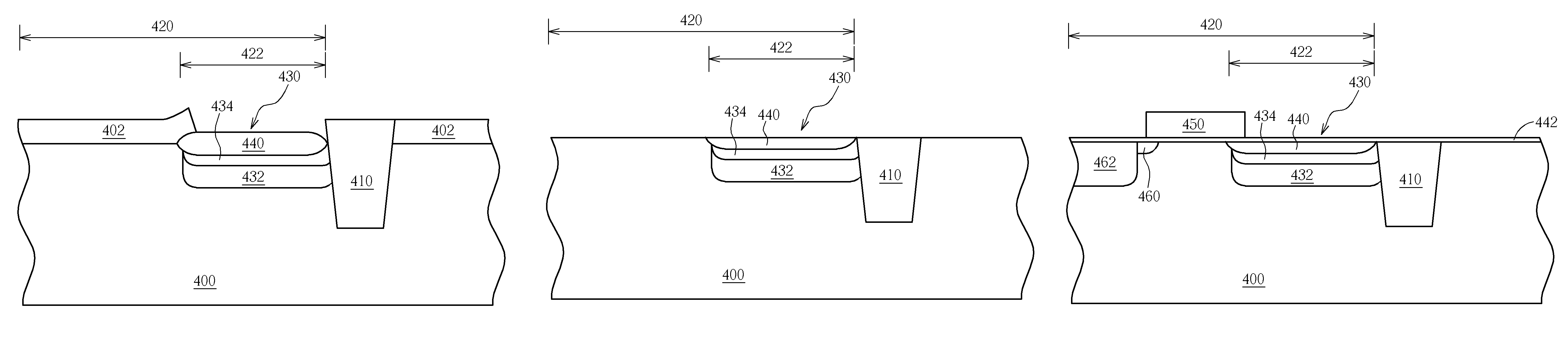
[0018]Please refer to FIGS. 3-10 which are schematic drawings illustrating the method for manufacturing an image sensor according to one embodiment in the present invention. As shown in FIG. 3, a substrate 300 is first provided and a patterned hard mask layer 302 such as a composite layer comprising a pad oxide layer and a silicon nitride layer is formed on the surface of the substrate 300 for defining a position of a shallow trench isolation (STI) 310 (shown in FIG. 5). Then a dry etching process is performed to etch the substrate 300 through the patterned hard mask layer 302 and to form a shallow trench 304 having a depth in a range of 3000-4000 angstroms.

[0019]Please refer to FIGS. 4-5. Then a thermal oxidation process, a spin-on process, or a chemical vapor deposition (CVD) process is performed to form a dielectric layer 306 filling the shallow trench 304 on the substrate 300. And a chemical mechanical polishing (CMP) method is performed as a planarization process to remove the ...


PUM


Abstract

A semiconductor substrate is provided on which a plurality of shallow trench isolations (STI) defining a plurality of active areas are formed. The active areas comprise a photo sensing region, and a plurality of photodiodes are formed in each photo sensing region. Then a local oxidation of silicon isolation (LOCOS) layer is formed by performing a LOCOS process. Thereafter a plurality of gates are respectively formed in each active area, where the gates partially overlap the LOCOS layer. Finally doped regions are formed in the semiconductor substrate where the gate does not cover the LOCOS layer.

Description

BACKGROUND OF THE INVENTION [0001]1. Field of the Invention[0002]This invention relates to an image sensor device and a manufacturing method thereof, and more particularly, to a complementary metal-oxide semiconductor (CMOS) image sensor having pinned photodiode (PPD).[0003]2. Description of the Prior Art[0004]Complementary metal-oxide semiconductor (CMOS) image sensors are manufactured by using conventional semiconductor techniques, which have the advantages of low cost and small size. Furthermore, the CMOS image sensors have high quantum efficiency and low read-out noise. Therefore CMOS image sensor has become a prevailing image technology and replaces the charge-coupled device (CCD) over time.[0005]A typical CMOS image sensor comprises a photodiode for sensing light. Light current from the photodiode induced by light represents a signal, whereas dark current generated from the photodiode in the absence of light represents noise. The photodiode processes signal data by using the v...

Claims


Application Information

Patent Timeline
Patent Type & Authority Patents(United States)
IPC IPC(8): H01L27/148H01L21/00
CPCH01L27/1463H01L27/14643H01L27/14689H01L27/14609Y10S438/981
Inventor SZE, JHY-JYI
Owner MARLIN SEMICON LTD
Why Eureka
Try Eureka