Synthesis of composite nanofibers for applications in lithium batteries

a lithium battery and composite nanofiber technology, applied in the field of composite nanofiber synthesis, can solve the problems of limiting production and applications, high cost of fabrication process, and single material nanofibers that cannot meet the application requirements, and achieve precise control, high quality, and cost reduction

Inactive Publication Date: 2008-01-29
IND TECH RES INST
View PDF10 Cites 9 Cited by
  • Summary
  • Abstract
  • Description
  • Claims
  • Application Information

AI Technical Summary

Benefits of technology

[0013]The method of “secondary template” of the invention is capable of producing high quality composite nanofibers and providing precise controls to the constructions, dimensions and chemical compositions of the nanofibers. The process reduces the cost, and provides nanofibers of small size, high weight energy density and high recharge and discharge efficiencies that meet the requirements of minimization of future products. The composite nanofibers can be applied to extensive scopes of micro electromechanical devices, micro integrated circuits and biochips, etc.

Problems solved by technology

However, the fabrication process is costly and energy intensive that limits the production and applications.
However, a single material nanofiber usually cannot meet the application requirements.
For example, in the application of lithium-ion secondary batteries, the Martin research group found that SnO2 nanofibers for negative pole material of a lithium cell, though having a high reversible electric capacity larger than 700 mAh / g and high current discharge rate of 58 C, has a high irreversible electric capacity that limits the applications.
The high irreversible electric capacity increases the surface impedance and decrease the lifetime of the nanofibers.
However, though the fabrication of single material nanofiber is easier, when forming a second material coating on exterior of the first nanofiber through conventional chemical vapor deposition or chemical impregnation, the coating is uneven in thickness and hard to be obtained.
Therefore, bi-material nanofiber with even composition is a great difficulty of fabrication with conventional processes.

Method used


Image

  • Synthesis of composite nanofibers for applications in lithium batteries
  • Synthesis of composite nanofibers for applications in lithium batteries
  • Synthesis of composite nanofibers for applications in lithium batteries

Examples


Embodiment Construction

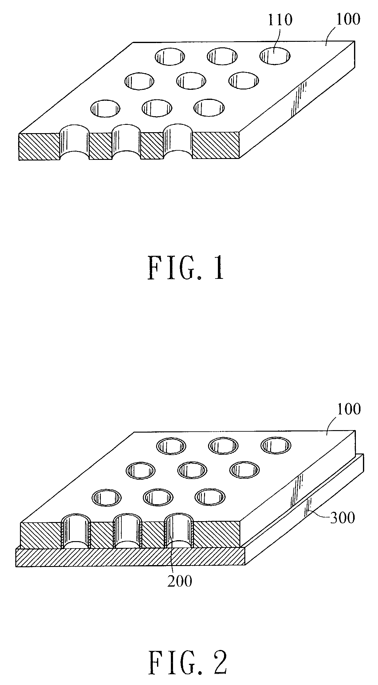
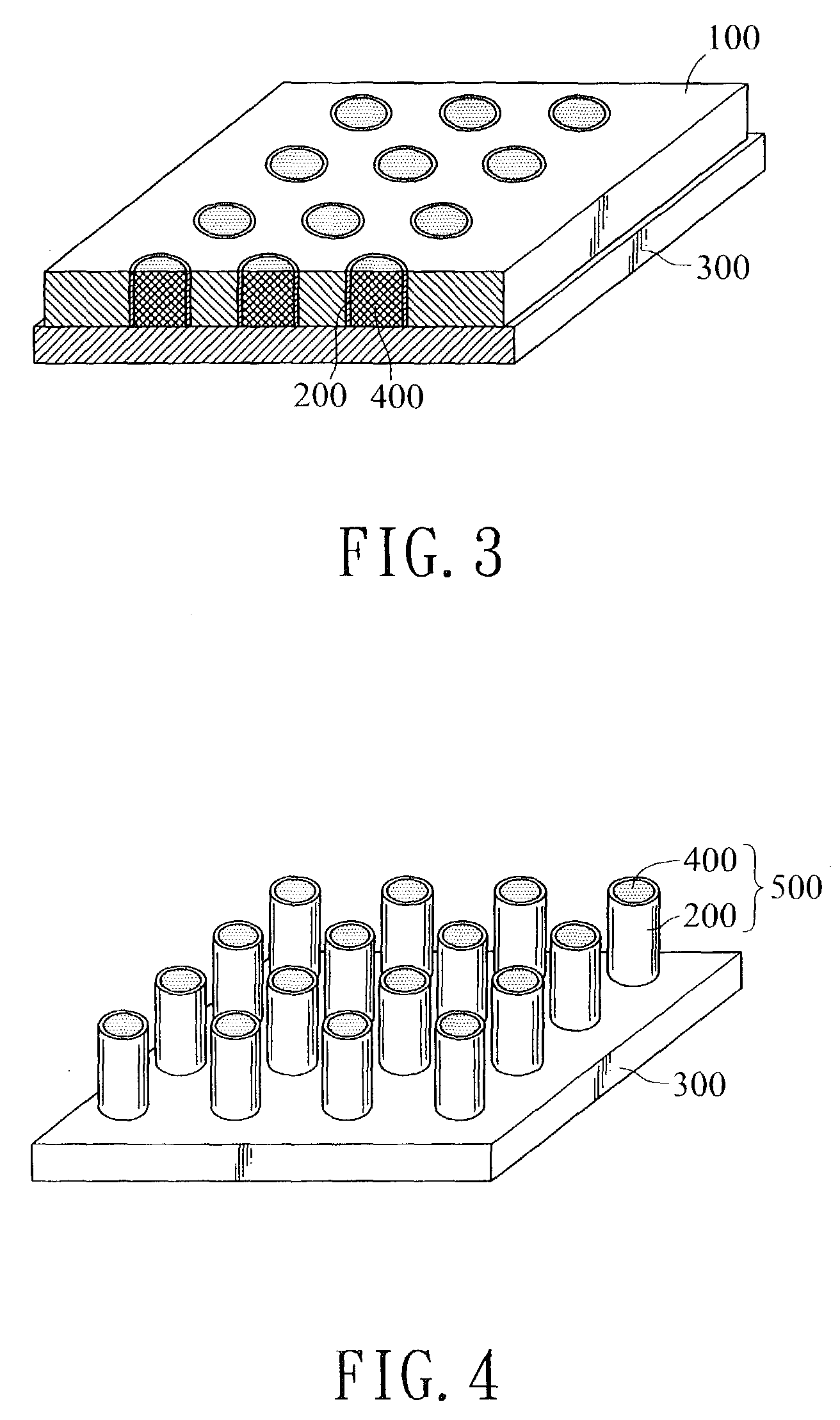
[0027]A process for fabricating composite nanofibers according to the invention is shown in FIGS. 1 to 4.

[0028]a) First, preparing a first tubular nanofiber. The first nanofiber is formed through a template 100 made of thin membrane of polycarbonate or anodic alumina and embedded with a first precursor (macromolecule, inorganic matter, metal oxide or carbon, etc) in the pores 110 of the template 100 through a method of sol-gel, chemical impregnation, electroless plating, electro-deposition or electron cyclotron resonance-chemical vapor deposition (ECR-CVD). The thickness of the hollow tubular nanofiber is controlled in accordance with the method and the parameters. For example, in sol-gel, the concentration, pH scale and soakage time are attended. In ECR-CVD, the vapor volume, deposition time and the kind of catalyst are attended. In electroless plating, the concentration, reaction time, pH scale and temperature are noticed. In electro-deposition, the voltage, current, time and pH s...


PUM

PropertyMeasurementUnit
aspect ratiosaaaaaaaaaa
diametersaaaaaaaaaa
diametersaaaaaaaaaa

Abstract

Methods of fabricating one-dimensional composite nanofiber on a template membrane with porous array by chemical or physical process are disclosed. The whole procedures are established under a base concept of “secondary template”. First of all, tubular first nanofibers are grown up in the pores of the template membrane. Next, by using the hollow first nanofibers as the secondary templates, second nanofibers are produced therein. Finally, the template membrane is removed to obtain composite nanofibers. Showing superior performance in weight energy density, current discharge efficiency and irreversible capacity, the composite nanofibers are applied to extensive scopes like thin-film battery, hydrogen storage, molecular sieving, biosensor and catalyst support in addition to applications in lithium batteries.

Description

BACKGROUND OF THE INVENTION[0001]This nonprovisional application claims priority under 35 U.S.C. § 119(a) on Patent Application No(s). 091137905 filed in TAIWAN, R.O.C. on Dec. 30, 2002, which is(are) herein incorporated by reference.[0002]1. Field of the Invention[0003]The invention generally relates to a synthesis method of composite nanofibers, and particularly relates to a method for synthesizing composite nanofibers by forming a second nanofiber inside a first hollow nanofiber that plays as a secondary template.[0004]2. Related Art[0005]Recently, nanotechnology is extremely hot in industries. Many breakthroughs are obtained and undoubtedly cause great impacts to the industry. Among numerous nano-scale materials, nanofibers have excellent characteristics in their energy and photoelectric properties so as to be highly noticed.[0006]A general method for producing nanofibers is the vapor deposition for fabricating vapor-growth carbon fibers. A carbon fiber is a hollow tubular struc...

Claims


Application Information

Patent Timeline
Patent Type & Authority Patents(United States)
IPC IPC(8): B05D7/22C23C16/00H05H1/24D01F9/12
CPCD01F9/12Y10S977/89Y10S977/893Y10S977/891Y10S977/892
Inventor CHEN, JIN-MINGHSIEH, CHIEN-TEHUANG, HSIU-WENHUANG, YUE-HAOLIN, HUNG-HSIAOLIU, MAO-HUANGLIAO, SHIH-CHIEHSHIH, HAN-CHANG
Owner IND TECH RES INST
Why Eureka
Try Eureka