Terahertz radiation sensor and imaging system

a radiation sensor and imaging system technology, applied in the field of terahertz radiation sensing apparatus and methods, can solve the problems of difficult to detect radiation in the terahertz part of the electromagnetic spectrum, affecting the commercialization of this technology, and affecting the accuracy of the detection results, so as to facilitate the detection of terahertz radiation, facilitate the transmission of terahertz radiation, and accelerate the acquisition time

Inactive Publication Date: 2008-02-05
CRAWLEY DAVID ALEXANDER
View PDF22 Cites 36 Cited by
  • Summary
  • Abstract
  • Description
  • Claims
  • Application Information

AI Technical Summary

Benefits of technology

[0021]Preferably the first and second optical paths traverse the detector, which may comprise an electro-optic crystal, and are preferably substantially counter propagating within the detector. Preferably the polarizer / beam splitter comprises a polarizing beam splitter. Using a single polarizing beam splitter to both direct light onto and filter light from a detector such as an electro-optic crystal facilitates the construction of a probe head with a high extinction ratio, for example of the order of 1:106. In embodiments such a configuration also facilitates fabrication of a compact and rugged probe head, as well as potentially reducing the bill of materials for the device. In embodiments the configuration also allows objects to be placed directly in front of the terahertz detector, allowing for near field imaging (Section 10.1.2 on page 437 of Optics (third edition) by Eugene Hecht describes near field (or Fresnel) diffraction and far field (or Fraunhofer) diffraction; the regimes are the same for imaging), for example where back-reflection of the probe beam by the detector is employed. Furthermore situating a polarizing beam splitter, for example comprising two trapezoid prisms, such that it both directs a probe pulse onto an electro-optic sampling crystal and filters the output from the EOS crystal makes the sensor relatively insensitive to vibration, and in embodiments, in effect makes the sensor system self-aligning.
[0023]The sensor is preferably configured so that the probe beam is internally reflected off a front face of the detector. This face of the detector may be provided with an optical filter to filter out ambient light which might otherwise reach the photosensitive detector and / or a multi layer stack to enhance transmission of terahertz radiation into the detector.
[0024]Preferably the photosensitive detector comprises an imaging sensor such as a CCD (charge coupled device) or CMOS (complimentary metal oxide semiconductor) sensor. Employing a photosensitive array facilitates the detection of terahertz radiation at a plurality of pixels simultaneously (area detection). This has a number of advantages in embodiments, for example, allowing faster acquisition times, allowing for single shot measurement of terahertz pulses making an imaging system less susceptible to interpulse variations and laser instability, and avoiding the need for a mechanical scanning system, thus reducing cost and complexity. A CMOS image sensing device is particularly preferred as this enables the use of higher probe beam chop rates (as described further later) thus reducing noise and improving sensitivity, as well as reducing cost and providing a more compact probe head (relative to use of a CCD sensor). Moreover in embodiments the use of CMOS detection as compared with conventional balanced diode detection can avoid the need for expensive lock-in device.
[0025]In some embodiments of the terahertz radiation sensor the sensor (front face) lacks a terahertz focusing system such as a lens or mirror and is a non-terahertz-imaging sensor (that is, the incoming terahertz radiation is not imaged, for example onto the detector). Thus the sensor may be configured that terahertz radiation falling on the detector is substantially unfocussed. This can further reduce cost and increase ruggedness and compactness of the sensor, as well as facilitating near field imaging in potentially hostile environments such as medical / veterinary endoscopic imaging. Near field imaging also potentially provides higher image resolution than available by other techniques.
[0037]Preferably, therefore, the terahertz sensor comprises a non-terahertz radiation imaging sensor—the terahertz detection plane (for example, the front surface of the sensor) need not be at or close to a terahertz imaging plane. The inventor has recognized that it is nonetheless possible to image an object without a physical terahertz imaging system. For example, as alluded to above, terahertz detection may be performed by phase-sensitive electro-optic sampling. As previously described in such an arrangement the probe radiation may be provided to the back of a detector crystal such an EOS crystal in order to create a phase sensitive imaging plane that can easily be sampled at multiple pixels, for example by means of a CMOS optical imaging array.
[0038]Preferably the terahertz source comprises an extended source rather than a point source. This facilitates perfusion of an object with terahertz radiation that will reach the detection plane. For some objects, such as a lens like object, perfusion of an object with terahertz radiation may be best achieved with a source that is point like, although in general a diffuse source is normally preferred.

Problems solved by technology

Zhang, Phys. Med. Biol. 47, 3667 (2002)), however commercialization of this technology has been hampered by a lack of rugged compact imaging systems that allow rapid acquisition of terahertz images.
It has traditionally been very difficult to detect radiation in the terahertz part of the electromagnetic spectrum.
Suitable detectors are typically very bulky, they often require cooling with cryogenic fluids (as with bolometric detection), and they are rarely robust and insensitive to vibration.
Further more there are significant problems with background noise.
It is difficult to exclude this noise in detection schemes.
One drawback relates to the sensitivity of the probe and more particularly to the size of the electro-optic response to terahertz radiation, which is very small.
This, coupled with the relative lack of efficiency of terahertz emitters can result in a need to measure a change in polarization of the order of 1 part in 104 to 1 part in 106.

Method used


Image

  • Terahertz radiation sensor and imaging system
  • Terahertz radiation sensor and imaging system
  • Terahertz radiation sensor and imaging system

Examples


Embodiment Construction

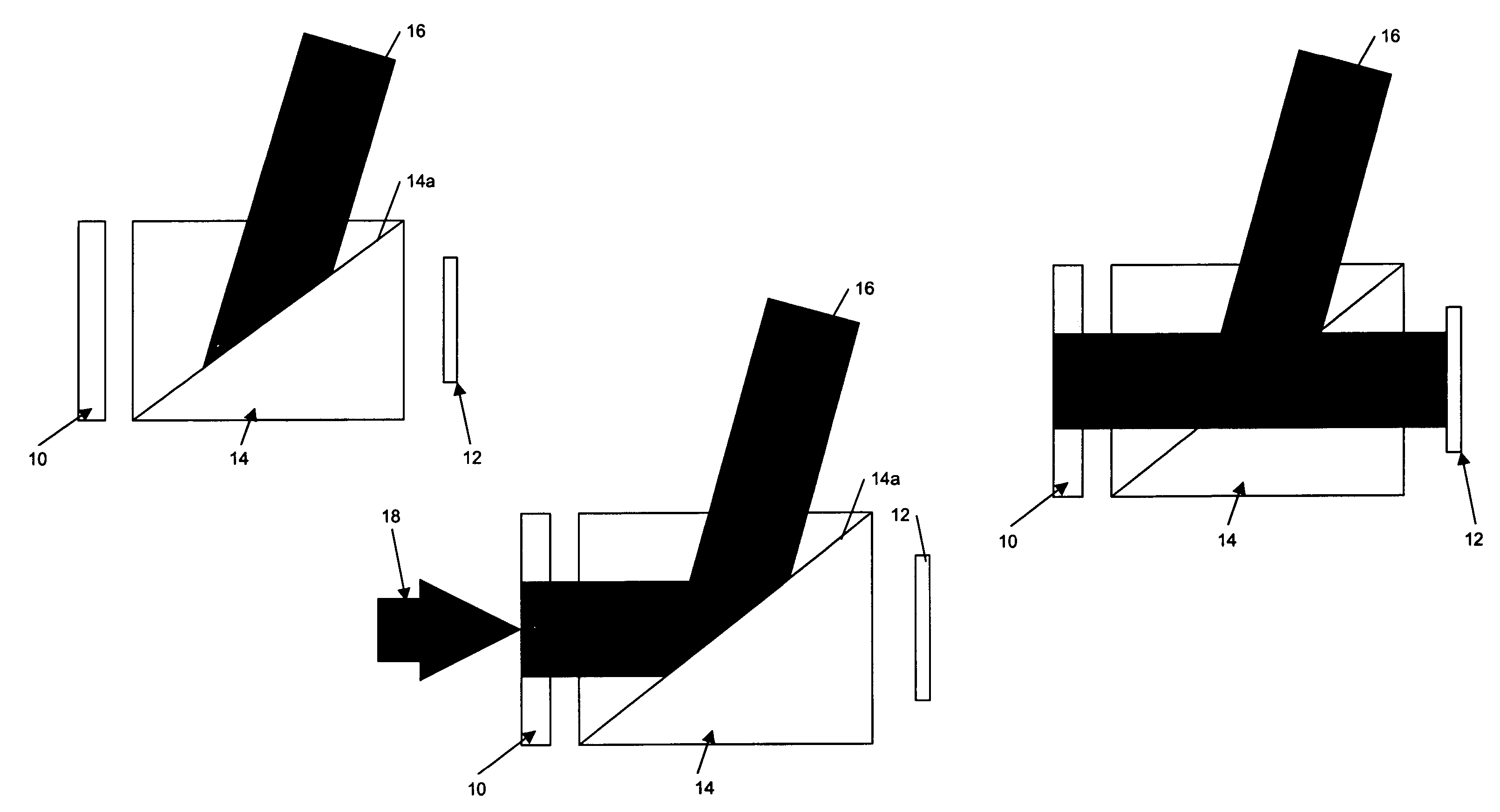
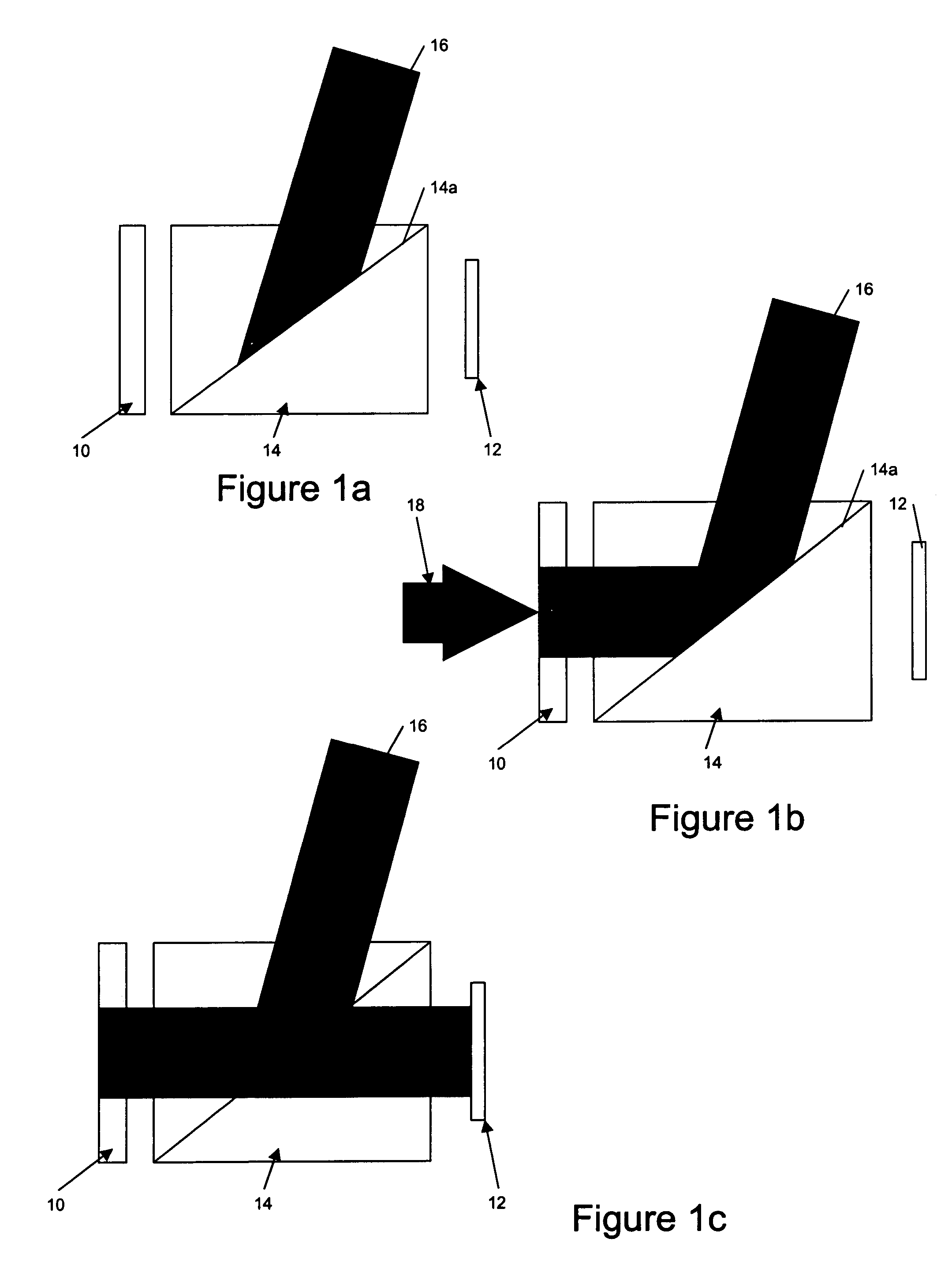
[0064]Referring to FIG. 1, a simplified terahertz radiation sensor comprises an electro-optic crystal terahertz radiation detector 10 and a photo-sensitive detector 12 between which an optical path includes a polarizing beam splitter rhomboid 14, for example a glan-laser prism (which may or may not be Brewster cut). A probe beam 16 enters the radiation sensor and is reflected by an internal interface 14a of the prism and polarized (FIG. 1a). The polarized probe beam then passes from the beam splitter 14 on to the electro-optic sampling (EOS) crystal 10, the probe beam 16 passes through the EOS crystal and is internally reflected at its front face timed to coincide with the arrival in the EOS crystal of a pulse of terahertz radiation 18 (FIG. 1b). The terahertz pulse induces a change in the birefringence of the EOS crystal such that the polarization of parts of the probe beam changes. The probe beam 16 passes through the EOS crystal and is internally reflected at its front face, then...


PUM

PropertyMeasurementUnit
refractive indexaaaaaaaaaa
frequenciesaaaaaaaaaa
optical pathsaaaaaaaaaa

Abstract

This invention relates to apparatus and methods for sensing terahertz radiation, in particular over an area, and to terahertz radiation imaging systems.A terahertz radiation sensor, the sensor comprising an optical beam input to receive an optical probe beam, a detector to modulate said probe beam responsive to terahertz radiation, and a photosensitive detector to provide an output responsive to said probe beam modulation. The sensor being configured to provide a first optical path between said optical beam input and said electro-optic detector and to provide a second optical path between said electro-optic detector and said photosensitive detector, and wherein said sensor further comprises a polarizer, said polarizer being located in both said first and said second optical paths. We further describe imaging systems for use with such a probe.

Description

CROSS-REFERENCE TO RELATED APPLICATIONS[0001]This application claims the benefit of Great Britain application GBP290114 filed on 19 Jan. 2004.FEDERALLY SPONSORED RESEARCH[0002]Not ApplicableSEQUENCE LISTING OR PROGRAM[0003]Not ApplicableBACKGROUND OF THE INVENTION—FIELD OF THE INVENTION[0004]This invention relates to apparatus and methods for sensing terahertz radiation, in particular over an area, and to terahertz radiation imaging systems.BACKGROUND OF THE INVENTION[0005]The terahertz (THz) region of the electromagnetic spectrum spans the frequency range between the mid-infrared and the millimeter / microwave portion of the spectrum. In this specification, terahertz radiation is considered to be that lying within a frequency range of from 0.01 THz to 100 THz. In this specification we will also refer to light and to optical paths; it is to be understood that this includes non-visible light such as infrared and ultra violet light.[0006]Terahertz systems have shown much promise in rece...

Claims


Application Information

Patent Timeline
Patent Type & Authority Patents(United States)
IPC IPC(8): G01J5/02G01J3/433G01N21/35G01N21/45
CPCG01J3/4338G01N21/3581G01J3/0224G01N21/453G01N2021/1772G01N2021/1785G01N2021/3595G01N2201/064
Inventor CRAWELY, DAVID ALEXANDER
Owner CRAWLEY DAVID ALEXANDER
Why Eureka
Try Eureka