
Plasma radiation source and device for creating a gas curtain for plasma radiation sources

a radiation source and plasma technology, applied in the direction of photomechanical equipment, instruments, nuclear engineering, etc., can solve the problems of limiting the lifetime of the required optics, rotating foil structures, and respecting the suitability for storage under vacuum, so as to achieve optimal conversion efficiency and increase the life of the optics which is limited by the influence of debris

Inactive Publication Date: 2008-02-12
USHIO DENKI KK
View PDF10 Cites 12 Cited by
  • Summary
  • Abstract
  • Description
  • Claims
  • Application Information

AI Technical Summary

Benefits of technology

[0015]Therefore, it is the primary object of the invention to improve plasma radiation sources of the type mentioned in the beginning in such a way that the lifetime of the optics which is limited by the influence of debris is appreciably increased. The steps to be taken should counteract the propagation of debris and accordingly make it possible for source schemes whose use was formerly prohibited for reasons pertaining to the lifetime of the optics to be used with optimal conversion efficiency.
[0020]The device used in the plasma radiation source for debris suppression works efficiently in such a way that “dirty” plasma radiation source schemes can also be used with high conversion efficiency. For example, tin plasma or lithium plasma could also be usable for EUV lithography.
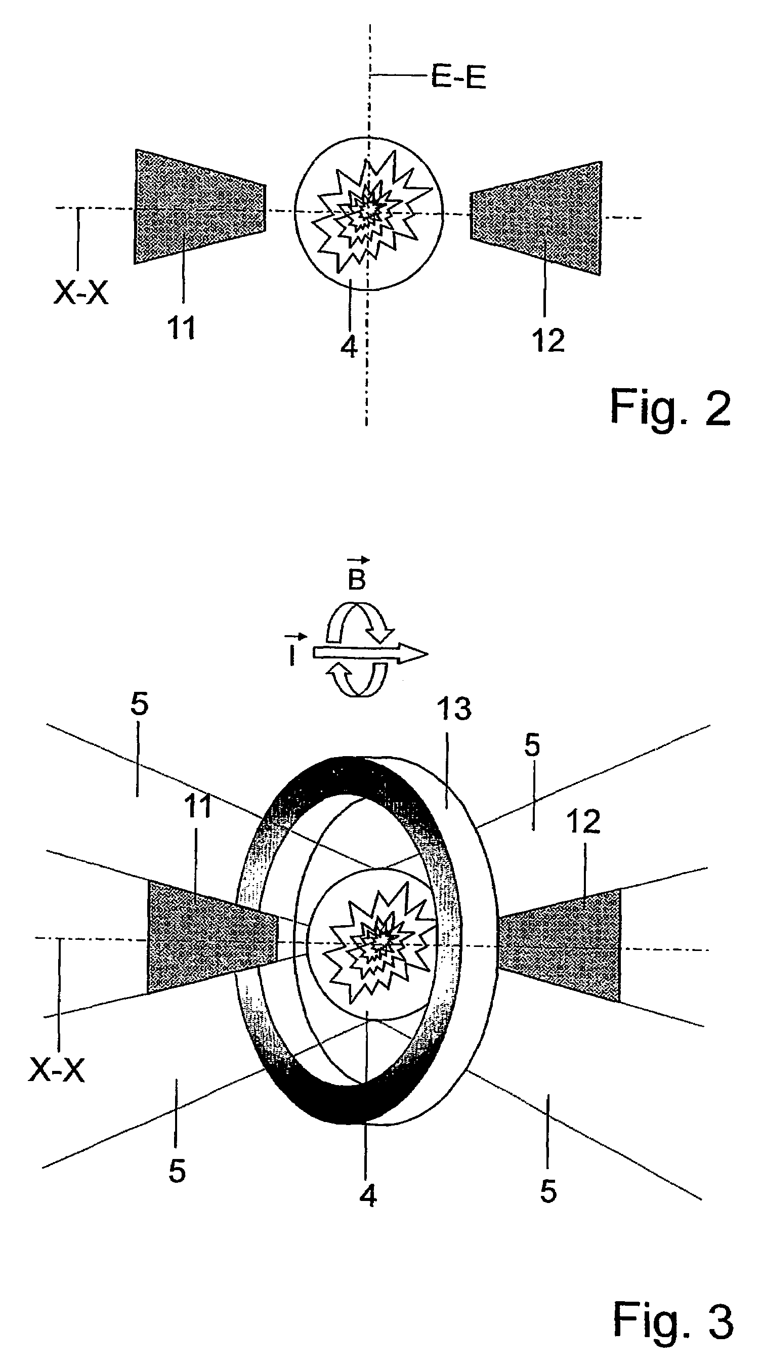
[0021]It is also advantageous when a pinch effect generated by the current flow along the axis is additionally supported by an external static or dynamic magnetic field around the plasma.
[0023]A particularly efficient use of the radiation emitted by the plasma is achieved when a reflector is provided adjacent to the source region along the axis of the mean propagation direction of the radiation, which reflector refocuses the radiation through the plasma. In this way, the usable solid angle can be doubled. The increase in usable radiation output that can be achieved in this way is limited by the reflectivity of the reflector and by absorption losses. The device for debris suppression, according to the invention, can also be used to protect this reflector in that the gas curtain is adjacent to the source region along the axis of the mean propagation direction of the radiation on both sides.

Problems solved by technology

This influence limits the lifetime of the required optics.
First, the plasma radiation source can be constructed in such a way that it generates as little debris as possible. This can be influenced, for example, by the type of plasma excitation (gas discharge, particle bombardment, laser excitation), by the design of the plasma environment, and by the choice of material composition of the plasma. Steps of this kind generate additional boundary conditions which frequently work against an optimization of the conversion efficiency. For example, xenon plasmas are often generated in plasma radiation sources for EUV lithography because xenon, as a noble gas, does not undergo any chemical changes and is not precipitated on surfaces. However, xenon is suboptimal from the view point of conversion efficiency in the wavelength range required for EUV lithography. Tin and lithium would be more favorable, but have rarely been used heretofore due to their low melting point and the high debris burden associated with it.
Second, active steps can be undertaken to protect the optics as far as possible from the damaging influence of debris.
Rotating foil structures present problems with respect to suitability for storage under vacuum, mechanical stability over occurring centrifugal forces and high-precision balancing due to the high rotational speeds on the order of 1000 m / s that are required for intercepting very fast particles.
Because of alignment tolerances, manufacturing tolerances and thermal loading, this requirement is often not met with sufficient precision in practice.
On the other hand, a sufficient suppression of debris is only achieved with high gas flow rates.
This leads to problems in the vacuum system and to loss of radiation output through gas absorption.
Similar problems can also occur in a device for x-ray irradiation according to EP 0 174 877 B1 which provides a flat flowing gas layer in front of an exit window of an evacuated chamber to protect a mask from particles.

Method used


Image

  • Plasma radiation source and device for creating a gas curtain for plasma radiation sources
  • Plasma radiation source and device for creating a gas curtain for plasma radiation sources
  • Plasma radiation source and device for creating a gas curtain for plasma radiation sources

Examples


Embodiment Construction

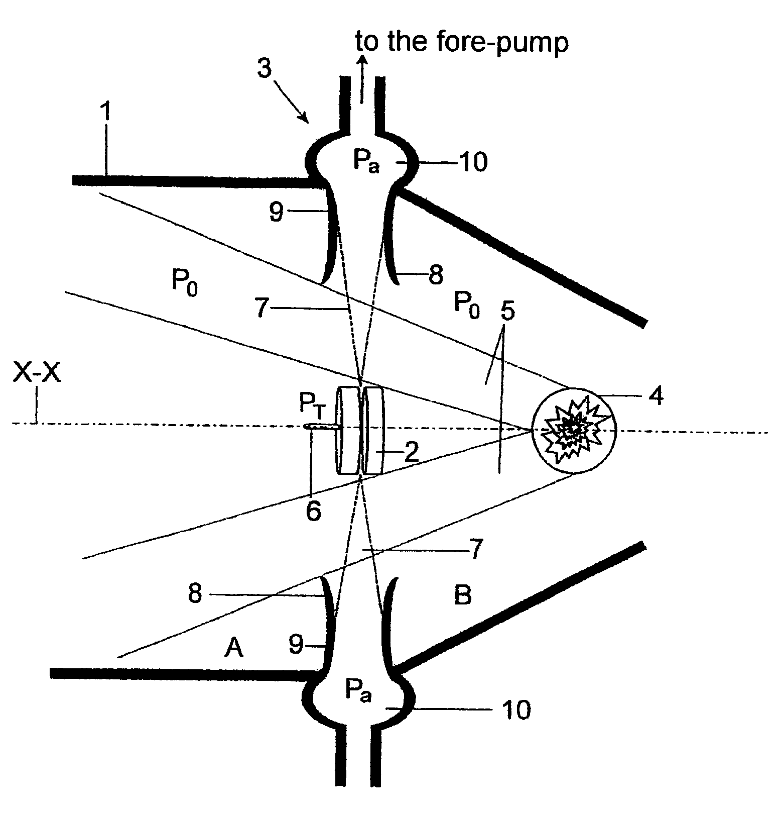
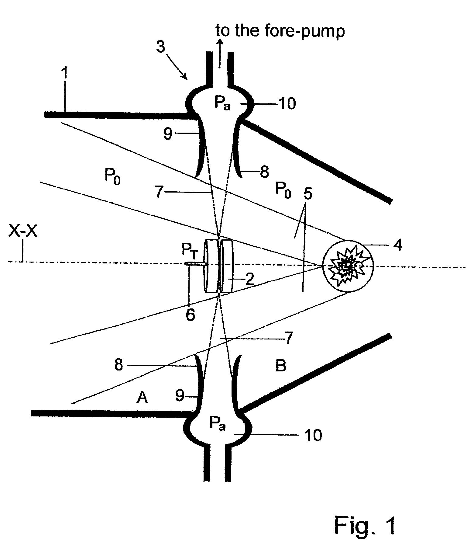
[0033]In the plasma radiation source shown in FIG. 1, a Laval nozzle serving as a propulsion nozzle 2 of a gas jet vacuum pump 3 is mounted in a vacuum chamber 1 on the axis X-X of the mean propagation direction of radiation 5 generated by a plasma 4.

[0034]The propulsion nozzle 2 is acted upon by an inert gas at a propulsion pressure PT through a supply channel 6 and generates a circular supersonic gas jet 7 that is directed on the radial outside to the chamber wall of the vacuum chamber 1. The supersonic gas jet 7, which can extend at right angles to or at some other angle to the axis X-X or which can also propagate conically, opens into an annular mixing nozzle 8 which tapers to an annular throat 9 and finally passes into the annular diffuser 10 of the gas jet vacuum pump 3. The diffuser 10 is evacuated to a gas pressure PG by one or more suitable vacuum pumps acting as fore-pumps. The gas jet vacuum pump 3 takes over two functions which are essential for the plasma radiation sour...


PUM

PropertyMeasurementUnit
solid angleaaaaaaaaaa
meltingaaaaaaaaaa
electrically conductiveaaaaaaaaaa

Abstract

A plasma radiation source is improved in such a way that the lifetime of the optics which is limited by the influence of debris is appreciably increased. A gas curtain through which the radiation proceeding from a source region in a vacuum chamber is emitted at a defined solid angle for debris suppression along an axis of the mean propagation direction of the radiation exits as a radially directed supersonic gas jet from a propulsion nozzle of a gas jet vacuum pump, which propulsion nozzle is arranged on the axis. The gas curtain is directed to an annular mixing nozzle that is arranged coaxial to the axis and is guided out of the vacuum chamber by a diffuser. This makes it possible to use source arrangements having an optimal conversion efficiency but extensive debris.

Description

CROSS-REFERENCE TO RELATED APPLICATIONS[0001]This application claims priority of International Application No. PCT / DE2004 / 001802, filed Aug. 9, 2004 and German Application No. 103 37 667.4, filed Aug. 12, 2003, the complete disclosures of which are hereby incorporated by reference.BACKGROUND OF THE INVENTION[0002]a) Field of the Invention[0003]The invention is directed to a plasma radiation source which emits radiation proceeding from a source region in a vacuum chamber along an axis of the mean direction of propagation of the radiation at a defined solid angle through a gas curtain that is provided for debris suppression.[0004]b) Description of the Related Art[0005]The invention is further directed to an arrangement for generating a gas curtain as a filter for particles in radiation whose mean propagation direction in a vacuum chamber extends along an axis directed through the gas curtain.[0006]Plasma radiation sources are used for generating short-wavelength electromagnetic radiat...

Claims


Application Information

Patent Timeline
Patent Type & Authority Patents(United States)
IPC IPC(8): G21G4/04G21G4/06G03F7/20H05G2/00
CPCG03F7/70908H05G2/003H05G2/005
Inventor SCHUERMANN, MAX C.SEHER, BERNDMUELLER, LUTZMISSALLA, THOMAS
Owner USHIO DENKI KK
Learn More