Optical component with spectral separation

a technology of optical components and spectral separation, applied in the field of optical components, can solve the problems of relative cost, achieve the effects of reducing x, increasing the ratio fwhm/, and reducing the physical space between the paths

Inactive Publication Date: 2008-02-26
EXFO OPTICS SAS
View PDF5 Cites 1 Cited by
  • Summary
  • Abstract
  • Description
  • Claims
  • Application Information

AI Technical Summary

Benefits of technology

[0006]One known method for increasing the ratio FWHM / Δλ therefore consists in using a planar wave guide-based concentrator to reduce Δx. This integrated optical component in effect makes it possible to reduce the physical space between the paths. This type of concentrator is particularly well suited for use in planar wave guide AWG (Array Wave Guide Grating) multiplexers / demultiplexers. However, it is relatively expensive.

Problems solved by technology

However, it is relatively expensive.

Method used


Image

  • Optical component with spectral separation
  • Optical component with spectral separation
  • Optical component with spectral separation

Examples


Embodiment Construction

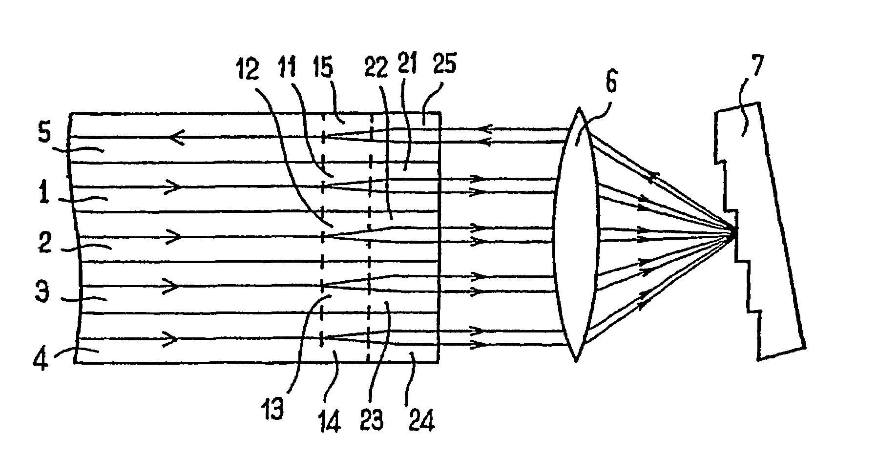
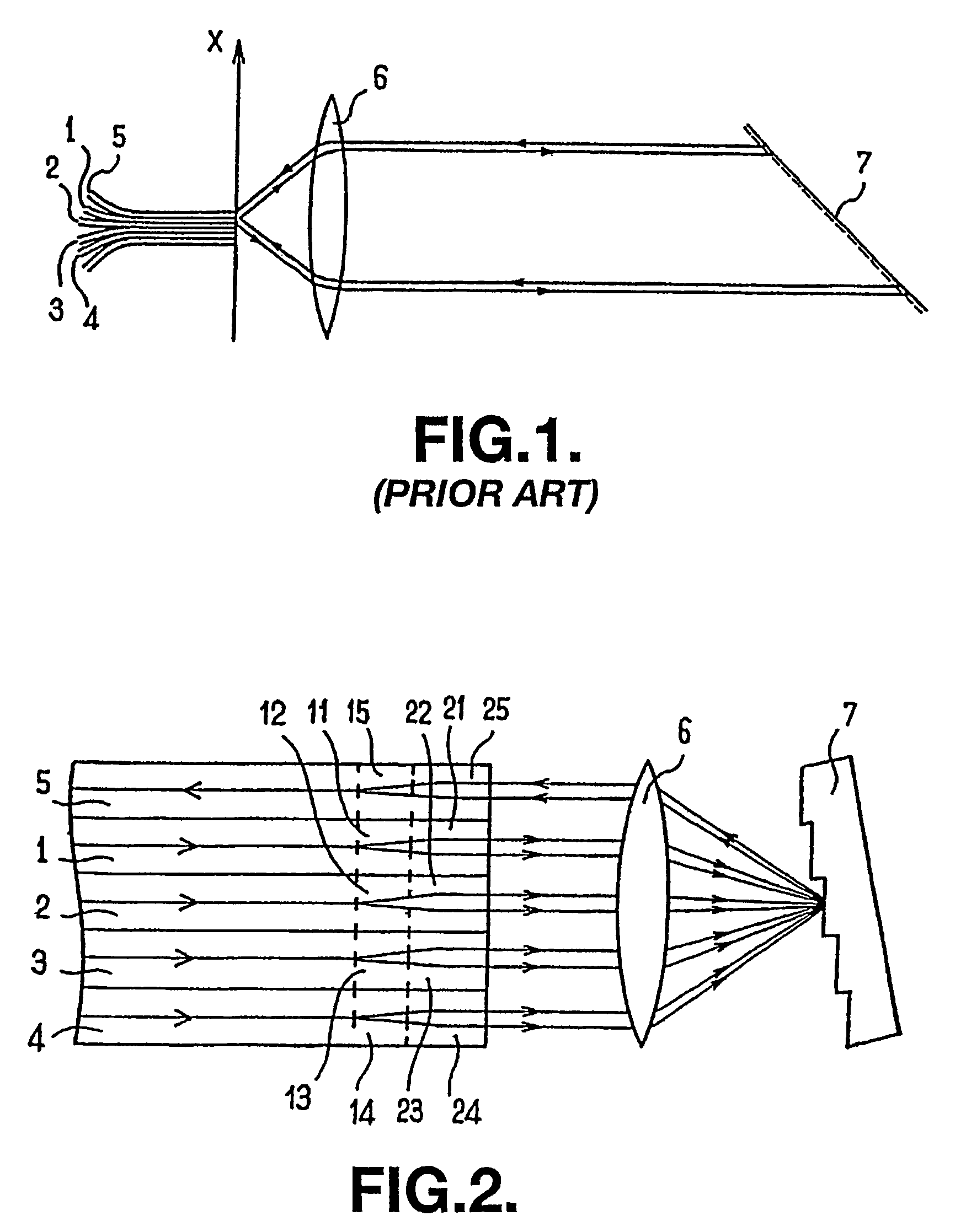
[0018]Of course this invention is not limited to the particular number of fibers illustrated in the appended figures, particularly to a 4 to 1 multiplexer, but extends to any component comprising n fibers.

[0019]The component represented in FIG. 2 operates like a multiplexer (this type of component could, of course, also be used as a demultiplexer). This component comprises coplanar optical fibers 1 to 5 that are parallel to one another and juxtaposed. Fibers 1 to 4 are input fibers, each dedicated to a given frequency band. Fiber 5 is an output fiber ensuring the transmission of the multiplexed optical beam obtained by superimposing the beams coming from the input fibers 1 to 4. The component also comprises a focusing element 6 of the lens type placed opposite the ends of fibers 1 to 5 and a diffractive element 7, for example a diffraction grating, that receives the signals coming from the input fibers 1 to 4 via the focusing element 6.

[0020]In known manner, the diffraction element ...


PUM


Abstract

The invention relates to an optical component comprising at least one input monomode fiber (1-4), at least one output monomode fiber (5) and a diffractive element (7) which is disposed between the input fiber or fibers (1-4) and the output fiber or fibers (5). The inventive component is characterized in that at least one of the input or output fibers (1-5) comprises a fiber (1-5) containing a portion (21-25) which is designed to increase the radius of the mode field it guides. According to the invention, the portion which is designed to increase the mode field radius can comprise a portion with a graded index, a portion having a core or cladding refractive index which varies transversely and/or longitudinally.

Description

BACKGROUND OF THE INVENTION[0001]The invention concerns the field of optical components and more particularly optical wavelength multiplexers and demultiplexers.[0002]The person skilled in the art knows that it is possible to considerably increase the traffic of fiber optic networks through wavelength multiplexing and demultiplexing techniques. Each series of data to be transported is transmitted over a specific optical frequency, multiplying the capacity of the fiber by the number of wavelengths used.[0003]FIG. 1 represents a multiplexer of the prior art. In this type of multiplexer, basic optical fibers 1 to 4 each dedicated to a frequency band have their end in a plane x constituting the input plane of the multiplexer. This multiplexer also comprises a collimation element 6 and a diffractive element 7. The input plane x of the multiplexer is confused with the focal plane of the collimation element 6 so that the input beams coming from the ends of the basic fibers 1 to 4 pass thro...

Claims


Application Information

Patent Timeline
Patent Type & Authority Patents(United States)
IPC IPC(8): G02B6/28G02B6/12G02B6/02G02B6/293G02B6/34G02B6/42
CPCG02B6/12016G02B6/2931G02B6/29362G02B6/29367G02B6/12019G02B6/2551G02B6/32G02B6/4203
Inventor FOUCHE', JEAN-BAPTISTE
Owner EXFO OPTICS SAS
Why Eureka
Try Eureka