Ultra-high temperature micro-electro-mechanical systems (MEMS)-based sensors

Inactive Publication Date: 2008-03-04
UNIV OF CENT FLORIDA RES FOUND INC
33 Cites 36 Cited by

AI-Extracted Technical Summary

Problems solved by technology

The development of smart materials and sensors has been challenging for some structures, such as gas turbine engines, space craft and the like, because they operate at extreme conditions of temperature, pressure, fluid (air/gaseous mixture, air/fuel mixture) velocity, and the like.
Direct measurement of hot gas properties at the exit of a gas turbine combustor and inlet of the first row of vanes or nozzles under actual operating conditions is quite difficult, if not impossible, with currently available measurement tools.
Temperatures at that location can be in excess of 1800° K, and the chemical conditions are quite hostile, rendering any off-the-shelf intrusive probe quite useless.
Also, because o...

Method used

[0049]FIG. 1 shows a conventional five-hole probe that is a fundamental instrument for measurement of mean velocity components in three-dimensional flows and the data obtained by such a probe is used to validate hot wire ad most of the advanced non-intrusive measurement methods such as, for example, Laser Doppler Velocimetry (LDV) and Particle Image Velocimetry (PIV), and even for validation of Computational Fluid Dynamic (CFD) codes. Such a probe registers pressures at its five holes located at the measuring tip once placed in a flow volume. The five holes are connected to pressure transducers, which in turn can be used to obtain velocity magnitudes and directions. The center tube, when aligned with the major velocity vector gives stagnation pressure while other tubes may, for example, give pseudo-static pressure(s) depending on the type of pressure sensor in use. Apart from the total pressure values, along with the pseudo-static pressure(s) all three vectors of mean velocity as well as the direction can be obtained from the sensor using its calibration curve(s). Basically, flow from a gas turbine is three-dimensional in nature, which requires a rugged and a simple tool to map flow-characteristics in various flow passages. Because the flow path in a turbine is of a complex geometry with narrow dimensions; a sensor with smaller dimensions may be used, for example, to increase the accuracy of measurement data. Typically conventional five-hole sensors are made of steel tubes. They have been found to have limitations in their application to the combusting flow measurements: (1) Being made of metal tubes, even with a provision of cooling, they have a limit in terms of temperature to withstand in a hostile, high temperature, combusting environment, (2) Conventional designs are not suitable for measurements in narrow complex flow passages where precise measurement is required.
[0053]The prongs 21 (support needles) on which the sensor 22 is welded or soldered have much higher conductivity as compared to the sensor in order to minimize additional resistance in the sensor circuit. The value of temperature sensitivity of electrical resistance for typical sensor materials are: Platinum=3.5×10⁻³(° C.)−1 and Tungsten=5.2×10⁻³(° C.)−1. All other sensors are quite standard. Pressure and shear stress sensors utilize piezo-restive property of the proposed amorphous material. All temperature sensors utilize temperature dependence of resistance as will be shown later.
[0066]Processability is made easier in embodiments of the PDCs disclosed in this invention. Due to the “glass-transition” temperature of the cross-linked polymer usually being greater than the pyrolysis temperature, the shapes formed in the plastic state are retained in the ceramic state. This leads to a flexible and cost-efficient approach to manufacture ceramic components and devices from these interesting materials. For example, the component can be shaped or formed in the organic form, just prior to pyrolysis, which will yield self-similar ceramic components upon pyrolysis. It is possible to fabricate high temperature fibers, protection coatings, and ceramic matrix composites. Most recently, the micro-fabrication techniques have been developed to fabricate ceramic by this unique material. FIG. 6 shows the scanning electron microscope (SEM) micrograph of SiCN ceramic micro-gear made by micro-casting technique.
[0070]Referring now to the design of the PDC sensors, which follows the basic principles of aerodynamics and heat transfer as applicable to the high temperature environment of a gas turbine. Each of the following designs optimize the respective sensor dimensions based on material properties so as to maximize the corresponding sensor sensitivity.
[0077]A fifth embodiment of the present invention is an integrated temperature/heat flux sensor shown in FIGS. 11A and 11B. This sensor is based on the principle of resistance temperature detector (RTD) sensors discussed above. Two RTD sensors 70 and 71 are used with an electrically insulating PDC with low thermal conduc...

Benefits of technology

[0020]Thus, in embodiments, one main objective of the present invention is to provide smart sensors that are not otherwise available for use in extreme conditions, such as, for example, a gas turbine engine. The sensors are the result of creative and judicious selection of material...

Abstract

Novel micro electro mechanical systems (MEMS)-based sensors for use in ultra-high temperature environments are disclosed. The MEMS-based sensors are derived from a class of polymer-derived ceramics selected from the group consisting of SiCN, SiBCN and SiAlCN. The materials of construction are such that, the sensors are capable of accurate, real-time, on-line and in-situ monitoring, suppression of combustion oscillations and detailed measurements in operating structures that have temperatures of from about 1500° K to about 2000° K, extreme pressures/turbulence and harsh chemical off gases. When the novel sensors are mounted on a hot gas path wall, such as, at a combustor exit, there can be a continuous monitoring of pressure pulses/oscillations, wall shear stress, temperature and surface heat flux.

Application Domain

Material heat developmentThermometers using electric/magnetic elements +5

Technology Topic

CeramicWall shear +7

Image

  • Ultra-high temperature micro-electro-mechanical systems (MEMS)-based sensors
  • Ultra-high temperature micro-electro-mechanical systems (MEMS)-based sensors
  • Ultra-high temperature micro-electro-mechanical systems (MEMS)-based sensors

Examples

  • Experimental program(6)

Example

[0071]As a first embodiment of the present invention, a wall shear sensor, also known as a floating element shear sensor, is shown in FIG. 7A. The design consists of a floating plate or element 30, eight tethers 31 and conducting wires 32 for connection. Four of the tethers sense any movement in the floating element due to side-to-side shear and the other four tethers sense any movement due to up-down shear. See the top view shown in FIG. 7B. The tethers work as mechanical supports for the plate as well as piezo-resistive resistors in the sensing-transduction scheme. For measurement shear in any direction, two of the four shear experience tension and the other two compression. Because of the piezo-resistive property of the material, the resistance of each tether changes under tension or compression, and this change in resistance is measured through a half-bridge configuration (as in strain gauges). A half-bridging electrical configuration assuming matched resistance, the output, ΔV, is given by
[0072] Δ ⁢ ⁢ V = V A ⁢ GA P 8 ⁢ ⁢ A T ⁢ E ⁢ τ
where VA is applied voltage, G the gauge factor, AP the area of the plate, Ai the cross-section area of the tether, E Young's modulus, and τ the shear stress to be measured. By measuring shear in two orthoganal directions (with the help of eight tethers) the direction of shear stress can be resolved. Through an array of this sensor, mounted around the circumference at the combustor exit, near wall flow-pulsation can be detected, which is very important for monitoring of combustion stability.

Example

[0073]A second embodiment, a wall pressure sensor, technically known as a simple piezo-resistive pressure sensor, is shown in FIGS. 8A and 8B. As in the wall shear sensors, the piezo resistive property of the base material is the key enabling factor for this ultra-high temperature sensor. Piezo resistive pressure sensor consists of a diaphragm 40, a sealed cavity 41, two piezo resistive strain gauges 42, 43 and conducting connections 44. Another two unloaded strain gauges would be mounted inside the sealed cavity so that they do experience any strain, but do experience the same environmental conditions. These latter two gauges 42, 43 will act as compensators, and all four gauges will operate on a full bridge circuit. Through an array of sensors mounted around the circumference at the combustor exit, pressure pulses can be detected, which is important for monitoring of combustion stability.

Example

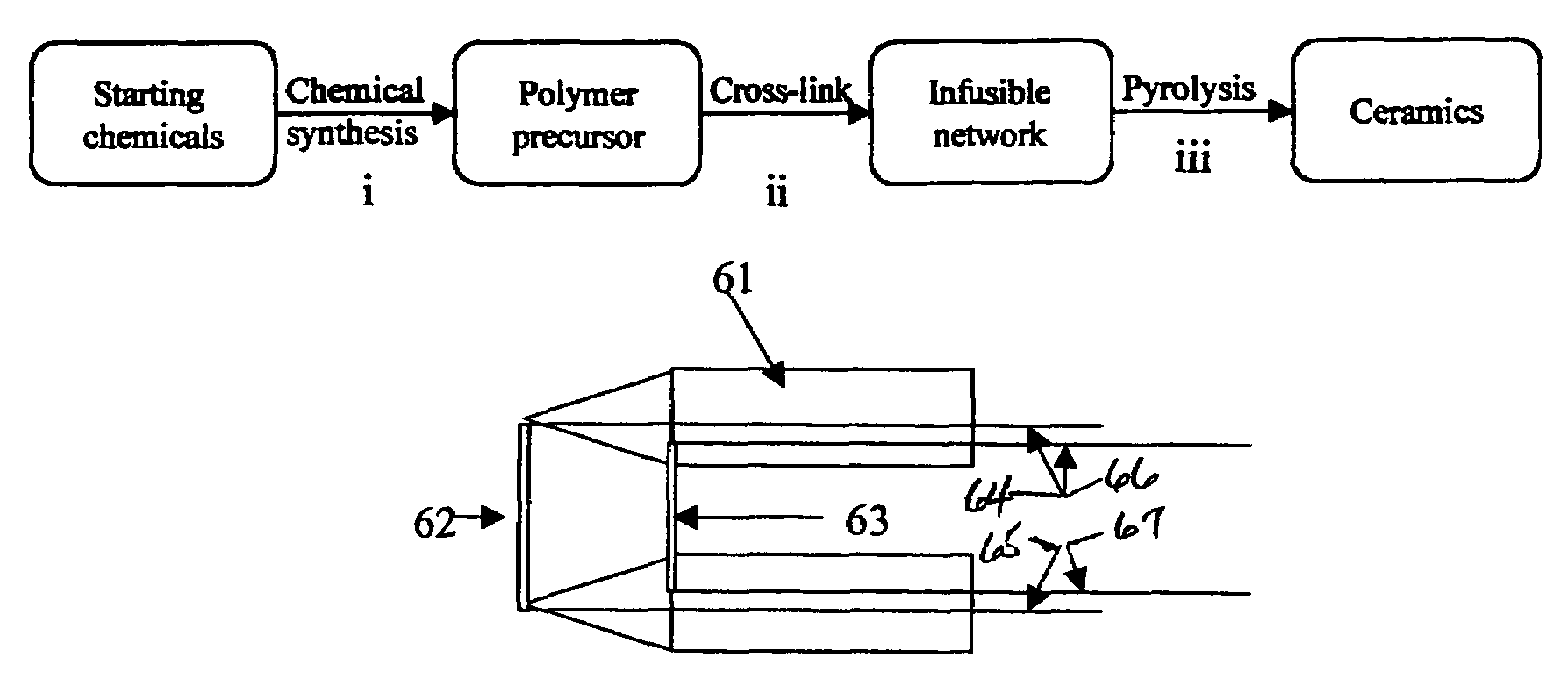
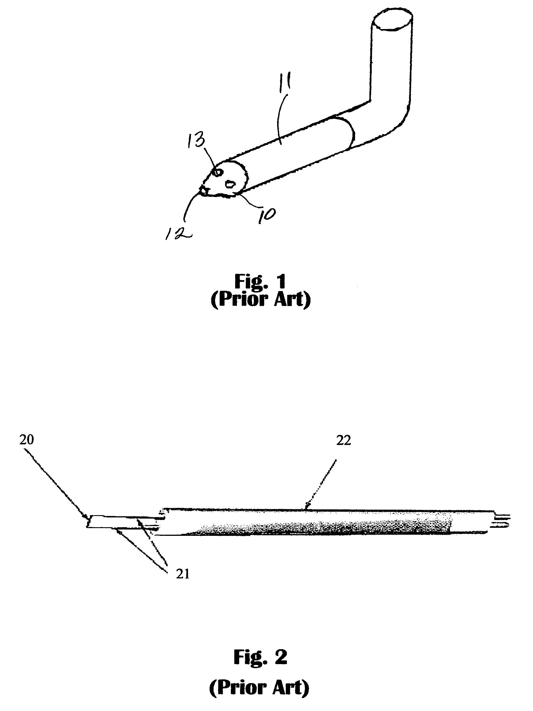
[0074]As a third embodiment, the design for a five-hole probe is shown in FIGS. 9A and 9B. A basic, conventional design of a five-hole sensor as described early and shown in FIG. 1, is modified with the inclusion of tip fences. The fences 50 have a conical side view and are described in more details under fabrication. The fences 50 allow the adaptation of ceramic micro-fabrication for the five-hole probe sensor.
[0075]Two side holes 51, 52 provide the yaw angle of the velocity vector, whereas holes above 54 and below 53 the center one 55 provide the pitch angle. All five holes provide together static and stagnation pressures. The design would involve determining all relevant dimensions so that no adverse aerodynamic effect is felt at the measurement tip. The hole and sensor diameters are subject to micro-fabrication limitations, and the frequency response needed. In this design, only mean value of velocity and pressures would be sought with the help of this probe.

PUM

no PUM

Description & Claims & Application Information

We can also present the details of the Description, Claims and Application information to help users get a comprehensive understanding of the technical details of the patent, such as background art, summary of invention, brief description of drawings, description of embodiments, and other original content. On the other hand, users can also determine the specific scope of protection of the technology through the list of claims; as well as understand the changes in the life cycle of the technology with the presentation of the patent timeline. Login to view more.

Similar technology patents

Fuel conditioning assembly

InactiveUS6915789B2reduce emissionless maintenance
Owner:ROYCE WALKER

Shopping cart

ActiveUS20060273536A1reduce numberless maintenance
Owner:THE ONDRASIK FAMILY TRUST DATED 11 3 1999

Multiple-use two-reservoir bucket

InactiveUS20070241049A1improve efficiencyless maintenance
Owner:TYTAR FR A

Anti-falling grounding fastening pile

ActiveCN112459047AEasy to install and useLess maintenance
Owner:STATE GRID JIANGSU ELECTRIC POWER CO LTD TAIZHOU POWER SUPPLY BRANCH +1

Classification and recommendation of technical efficacy words

  • less maintenance

Fuel conditioning assembly

InactiveUS6915789B2reduce emissionless maintenance
Owner:ROYCE WALKER

Multiple-use two-reservoir bucket

InactiveUS20070241049A1improve efficiencyless maintenance
Owner:TYTAR FR A

Shopping cart

ActiveUS20060273536A1reduce numberless maintenance
Owner:THE ONDRASIK FAMILY TRUST DATED 11 3 1999

Anti-falling grounding fastening pile

ActiveCN112459047AEasy to install and useLess maintenance
Owner:STATE GRID JIANGSU ELECTRIC POWER CO LTD TAIZHOU POWER SUPPLY BRANCH +1
Why Eureka
Try Eureka