Honeycomb structural body, manufacturing method of the honeycomb structural body, and exhaust gas purifying device

a technology of honeycomb and manufacturing method, which is applied in the direction of machines/engines, chemical/physical processes, domestic applications, etc., can solve the problems of reducing the efficiency of particulate collection, displacement of honeycomb filter, and harm to the environment and the human body caused by particulates

Active Publication Date: 2008-03-25
IBIDEN CO LTD
View PDF64 Cites 95 Cited by
  • Summary
  • Abstract
  • Description
  • Claims
  • Application Information

AI Technical Summary

Benefits of technology

[0036]The honeycomb structural body of the present invention has high strength (large durability) against thermal shock, and is less likely to generate cracks and damage and has excellent durability even in the case where a high pressure is applied to an outer peripheral face thereof.
[0015]In the honeycomb structural body, desirably, when at least three points are determined as the centers-of-gravities c2 of the least square curves in the length direction of the ceramic block, these centers-of-gravities c2 are not present on a straight line in parallel with the length direction of the ceramic block. Also desirably, when at least three points are determined as the centers-of-gravities c1 of the least square curves in the length direction of the honeycomb structural body, these centers-of-gravities c1 are not present on a straight line in parallel with the length direction of the honeycomb structural body.
[0020]A second aspect of manufacturing method of a honeycomb structural body according to the present invention is a manufacturing method of a honeycomb structural body comprising a pillar-shaped ceramic block in which a plurality of porous ceramic members are combined with each other through a sealing material layer, said porous ceramic member including a large number of through holes placed in parallel with one another in a length direction with a partition wall interposed therebetween, wherein the method comprises a step of: performing extrusion molding to form a plurality of kinds of ceramic molded bodies having different cross-sectional shapes.
[0205]Therefore, the exhaust gas purifying device of the present invention has excellent isostatic strength and push-out strength. Even during use of the exhaust gas purifying device for a long period of time, an increase in pressure of exhaust gas flown into the casing, a temperature rise in the honeycomb structural body, or the like does neither decrease strength for holding the honeycomb structural body nor displace or rattle the honeycomb structural body. Accordingly, the exhaust gas purifying device of the present invention has excellent strength against thermal shock, and excellent durability as well.

Problems solved by technology

In recent years, a problem has been raised about harm to the environment and the human body caused by particulates contained in exhaust gas discharged from internal combustion engines of vehicles such as automobiles, buses, and trucks, and constitution machines and the like.
This structure might cause displacement of the honeycomb filter in the casing when pressure that is applied on the end face of the exhaust gas inlet side of the honeycomb filter is raised with an increase in collected amount of the particulates contained in the exhaust gas, or when the holding power of the honeycomb filter, generated by the mat-like holding sealing material, inside the casing is reduced due to expansion of the casing to a size larger than that of the honeycomb filter through heating to a high temperature.
Upon occurrence of displacement of the honeycomb filter inside the casing as described above, the length direction of the honeycomb filter might become non-parallel with the flowing direction of the exhaust gas to cause reduction in particulate collecting efficiency, or the honeycomb filter might be brought into contact with the casing to generate cracks in the honeycomb filter.
Further, the mat-like holding sealing material might droop onto the end face of the exhaust gas inlet side of the honeycomb filter, closing the through holes exposed at this side to cause reduction in exhaust gas purifying efficiency.

Method used


Image

  • Honeycomb structural body, manufacturing method of the honeycomb structural body, and exhaust gas purifying device
  • Honeycomb structural body, manufacturing method of the honeycomb structural body, and exhaust gas purifying device
  • Honeycomb structural body, manufacturing method of the honeycomb structural body, and exhaust gas purifying device

Examples


example 1

[0207]70 parts by weight of α-type silicon carbide powder having an average particle size of 30 μm, 30 parts by weight of α-type silicon carbide powder having an average particle size of 0.28 μm, 5 parts by weight of methyl cellulose, 4 parts by weight of a dispersing agent, and 20 parts by weight of water were blended, and then mixed in a ball mill for 5 hours to prepare a uniform mixed composition.

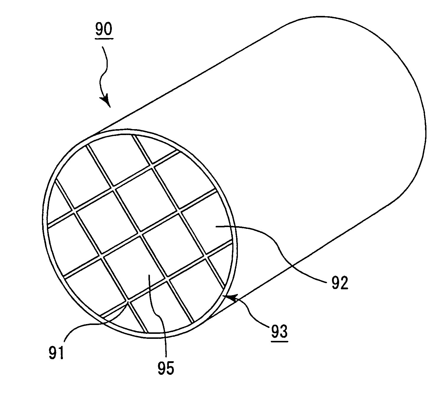
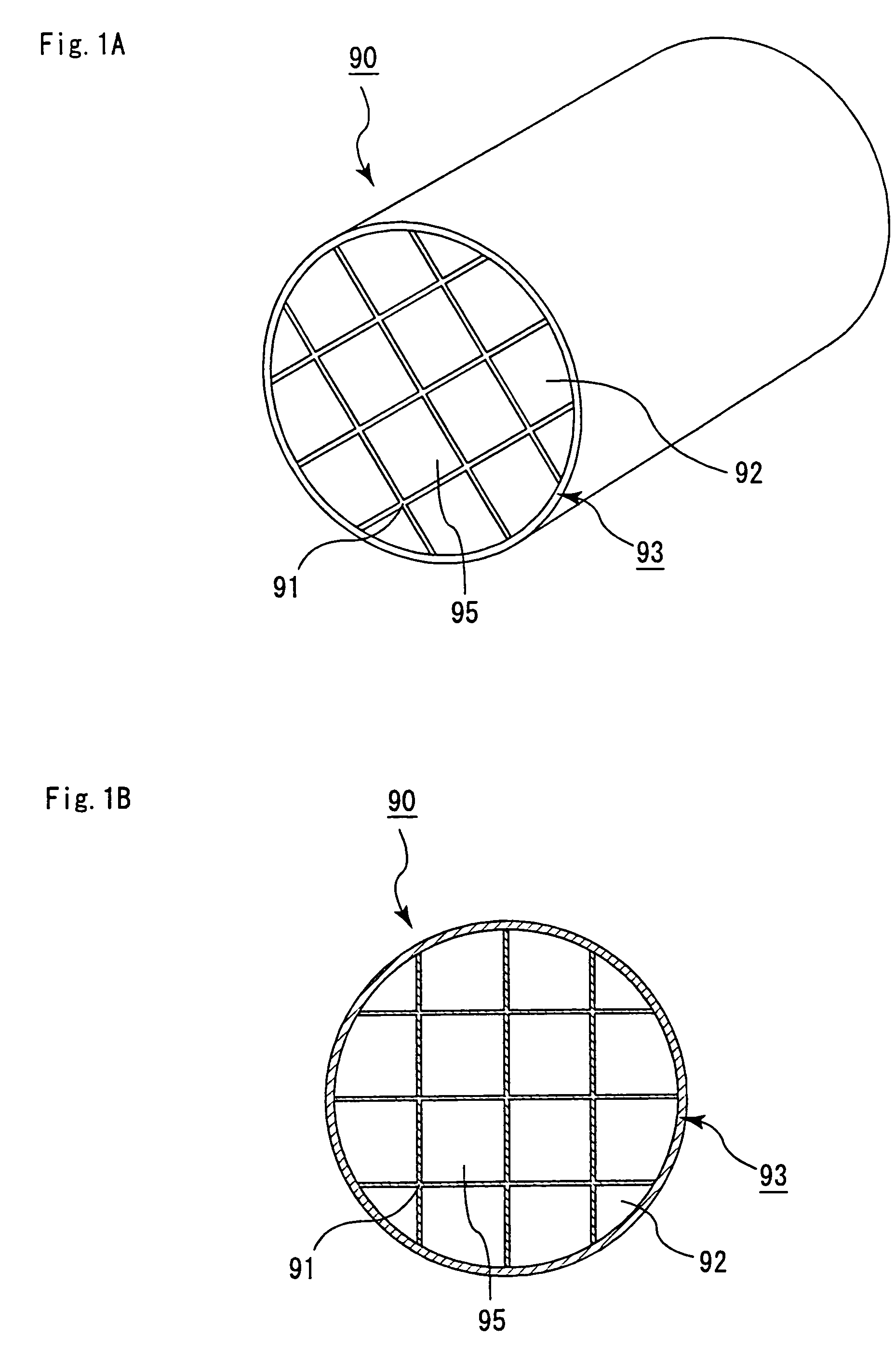
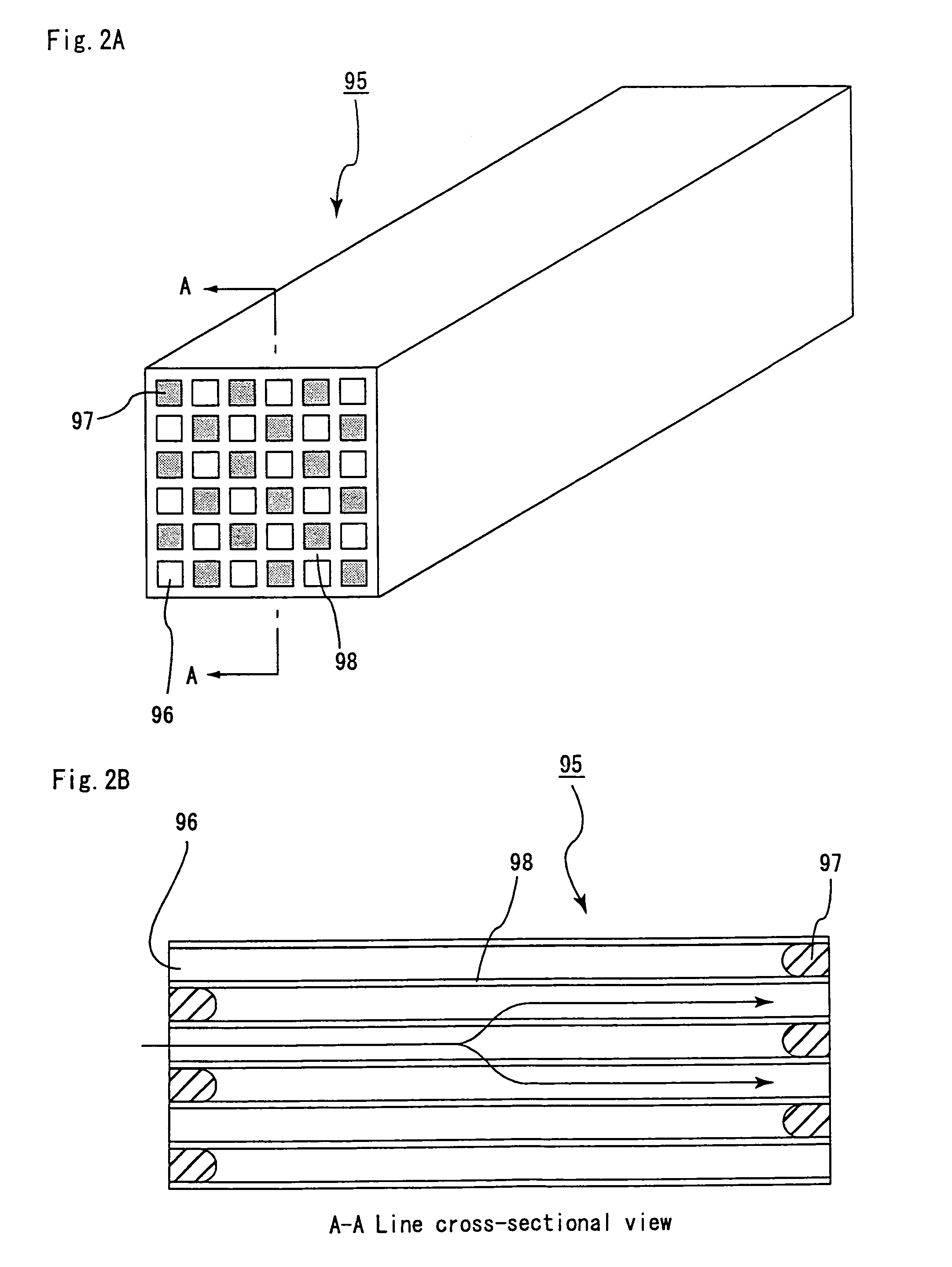
[0208]An extrusion-molding machine was filled with this resultant mixed composition, and at a push-out rate of 2 cm / min, a rectangular pillar-shaped ceramic molded body made of silicon carbide in honeycomb form was formed, which was almost the same as the porous ceramic member 20 shown in FIG. 4A. The ceramic molded body had a size of 35 mm×35mm×300 mm, the number of through holes of 31 / cm2 and a thickness of the partition wall of 0.35 mm.

[0209]The ceramic molded body was dried by a dryer, such as a microwave drier or a hot-air drier, to form a ceramic dried body made of silicon carbide,...

examples 2 to 11

, Reference Examples 1 to 4, and Comparative Examples 1 to 12

[0217]In the same manner as in Example 1, the resultant ceramic block and honeycomb structural body were processed to adjust irregularities on the surfaces thereof to form a honeycomb structural body (ceramic block) having M1 and M2 values as shown in Table 1.

[0218]It is to be noted that, in Examples 10 to 11, a ceramic block was formed in the same manner as in Example 1 except for using, as the sealing material (adhesive) paste, a heat resistant sealing material (adhesive) paste containing 30% by weight of alumina fibers having a fiber length of 20 μm, 21% by weight of silicon carbide particles having an average particle size of 0.6 μm, 15% by weight of silica sol, 5.6% by weight of carboxymethyl cellulose and 28.4% by weight of water, and the resultant ceramic block was processed to manufacture and process a honeycomb structural body. Further, in Comparative Example 1, a honeycomb structural body was manufactured in the ...

example 12

[0224]Next, a honeycomb structural body was manufactured in which a center-of-gravity c2 of a ceramic block and a center-of-gravity c1 of a honeycomb structural body were displaced from each other.

[0225]Specifically, in the same manner as in Example 1, a honeycomb structural body, with the M2 value set to 0.5 mm, was manufactured, and thereafter a honeycomb structural body, with the M2 value set to 0.5 mm, was manufactured by change in balance of thickness of the sealing material (coating) layer.


PUM

PropertyMeasurementUnit
porosityaaaaaaaaaa
porosityaaaaaaaaaa
porosityaaaaaaaaaa

Abstract

A honeycomb structural body comprising: a pillar-shaped ceramic block and a sealing material provided on an outer peripheral portion of said ceramic block, each of them having irregularities formed on an outer peripheral face wherein: when a least square curve is determined by a least square method on the basis of points constituting the contour of a cross-section, a center-of-gravity is defined as c1, a distance between a minimum concentric circumscribed curve having c1 and the center-of-gravity c1 is defined as D1, a distance between a maximum concentric inscribed curve having c1 and the center-of-gravity c1 is defined as D2, and the following inequality is satisfied: about 0.3 mm≦(D1-D2); same definition is applied to said ceramic block, a center-of-gravity thereof is defined as c2, a distance between a minimum concentric circumscribed curve having c2 and the center-of-gravity c2 is defined as D3, a distance between a maximum concentric inscribed curve having c2 and the center-of-gravity c2 is defined as D4, and the following inequality is satisfied: about 0.5 mm≦(D3-D4)≦about 7.0 mm.

Description

CROSS-REFERENCE TO RELATED APPLICATIONS[0001]This application claims benefit of priority to Japanese Patent Application No. 2004-111430, filed on Apr. 5, 2004, and PCT Application No. PCT / JP2004 / 019377 filed on Dec. 24, 2004. The contents of those Applications are incorporated herein by reference in their entirety.FIELD OF THE INVENTION[0002]The present invention relates to a honeycomb structural body, a manufacturing method of the honeycomb structural body, and an exhaust gas purifying device.DISCUSSION OF THE BACKGROUND[0003]In recent years, a problem has been raised about harm to the environment and the human body caused by particulates contained in exhaust gas discharged from internal combustion engines of vehicles such as automobiles, buses, and trucks, and constitution machines and the like. A variety of honeycomb filters have been proposed, in which exhaust gas is allowed to pass through porous ceramic, and particulates therein is then collected so that the exhaust gas is pur...

Claims


Application Information

Patent Timeline
Patent Type & Authority Patents(United States)
IPC IPC(8): B32B18/00B22F3/105B01D39/20B01D46/00B01D46/24B01D53/94B01J33/00B01J35/04C04B38/00F01N3/02F01N3/022F01N3/035F01N3/28
CPCB01D46/0001B01D46/2455B01J35/04C04B38/0006F01N3/0222F01N3/035F01N3/2828F01N3/2853B01D46/2429F01N3/2878C04B35/565C04B38/0074C04B38/008Y10T428/24149B01D46/2451B01D46/2466B01D2046/2433B01D2046/2481B01D2046/2492B01D2046/2496C04B2111/00793C04B2111/0081F01N2570/10F01N2570/12F01N2570/14B01D46/249B01D46/2486B01D46/24491B01D46/2498B01D46/2482B01D46/2478F01N3/28F01N3/02B01D39/20
Inventor YOSHIDA, YUTAKA
Owner IBIDEN CO LTD
Why Eureka
Try Eureka