Daytime stellar imager

a daytime stellar imager and imager technology, applied in the field of daytime stellar imagers, can solve the problems of large and heavy embodiments in the first set, and achieve the effects of reducing the number of received star photons, reducing the number of star photons, and reducing the signal-to-noise ratio (snr)

Inactive Publication Date: 2008-03-25
TREX ENTERPRISES CORP
View PDF7 Cites 86 Cited by
  • Summary
  • Abstract
  • Description
  • Claims
  • Application Information

AI Technical Summary

Benefits of technology

[0009]Systems designed by Applicants include very efficient optical sensors, which increase the probability of detecting stars during daytime by several orders of magnitude, as compared with a prior art approach based on CCD cameras operating at visible wavelengths. The latter is due to several factors including:
[0013]Additional advantages of this design approach are associated with the fact that atmospheric obscurants including haze and smoke affect infrared sensors less than sensors operating in the visible waveband, and the effect of daytime turbulence on the infrared sensor is lower.
[0015]Embodiments of the second set of preferred embodiments utilize telescopes with aperture diameter to less than 10 cm to provide much smaller and lighter systems. For example, with an aperture diameter of 5 cm, the dimensions of the system can be reduced to less than 20 cm×15 cm×12 cm. Such a system will fit applications of navigating missiles and aircraft. However, reduction of the telescope aperture diameter will reduce the number of received star photons and the signal-to-noise ratio (SNR). This will reduce the star detection limit, or star-limited magnitude. In addition, in order to avoid star image blur due to aircraft or missile motion and vibration, camera exposures on the order of a few milliseconds should be used. If the camera exposure is reduced to a few milliseconds, then once again the SNR is reduced. Applicants utilize two techniques to compensate for the above SNR losses caused by reduction of the telescope aperture diameter and camera exposure time. The first technique is to increase the star brightness by pointing a telescope to selected bright infrared stars. In preferred embodiments Applicants use a two-axis precision rotary stage to point one or more telescopes at selected bright stars. In these preferred embodiments Applicants limit the size of search windows to be equal, or less, than the 15°×15° square area angular distance over which the selected commercially available rotary stage maintains a one arc-second absolute accuracy or less. This provides an optical scan of up to 30°×30° when used with a reflecting mirror. The second approach is to utilize infrared cameras with reduced readout camera noise. Applicants have determined that for short camera exposures, the SNR is limited by the camera readout noise rather than the sky background noise. In some preferred embodiments an “all sky” CCD camera views the entire sky so that on “partly cloudy days the telescope can be quickly pointed to a cloudless region of the sky.

Problems solved by technology

Embodiments in this first set tend to be relatively large and heavy, such as about one cubic meter and about 60 pounds.
Also these embodiments work in those areas with poor GPS coverage or where GPS is not available at all.

Method used


Image

  • Daytime stellar imager
  • Daytime stellar imager
  • Daytime stellar imager

Examples


first compact embodiment

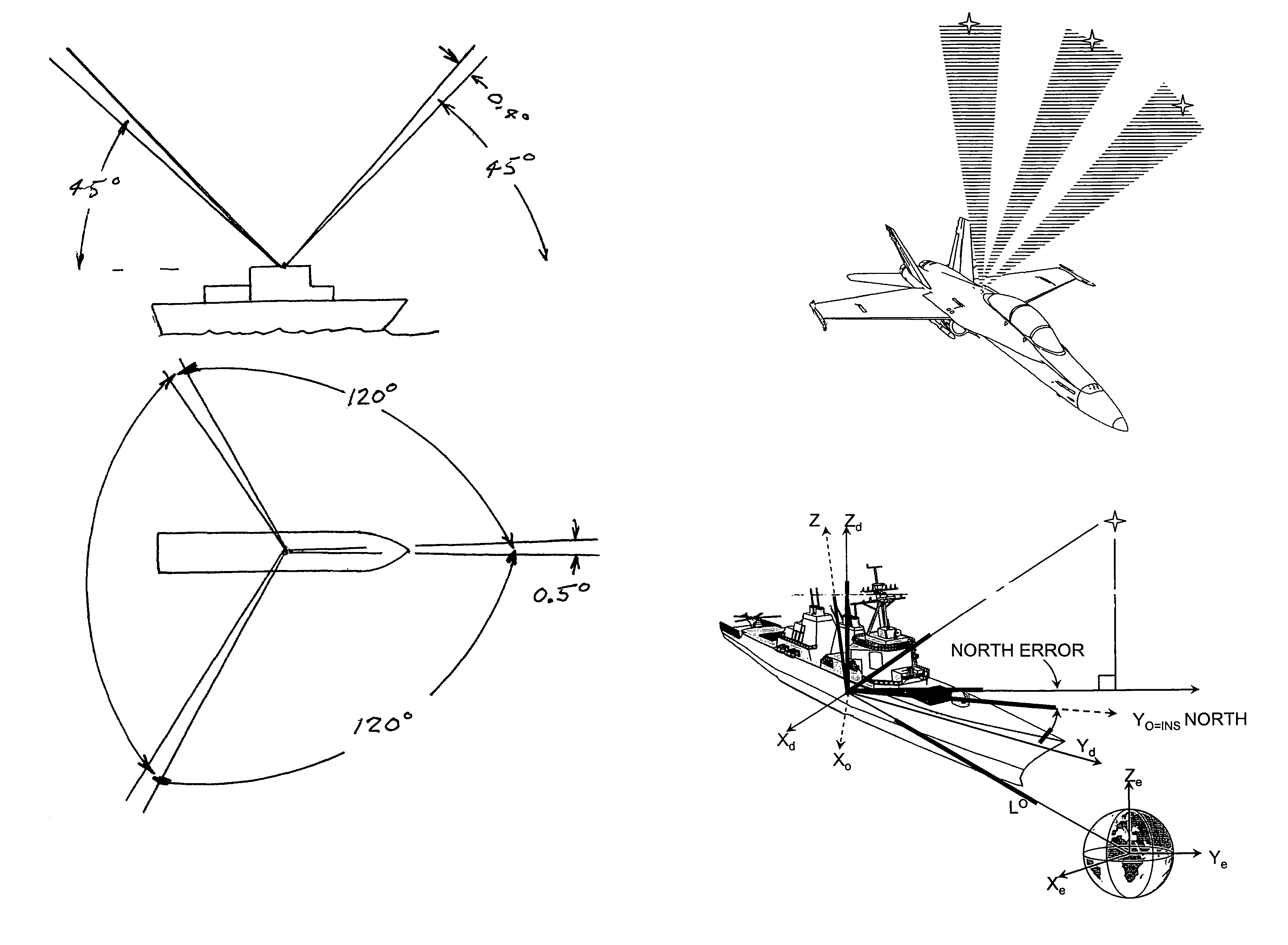
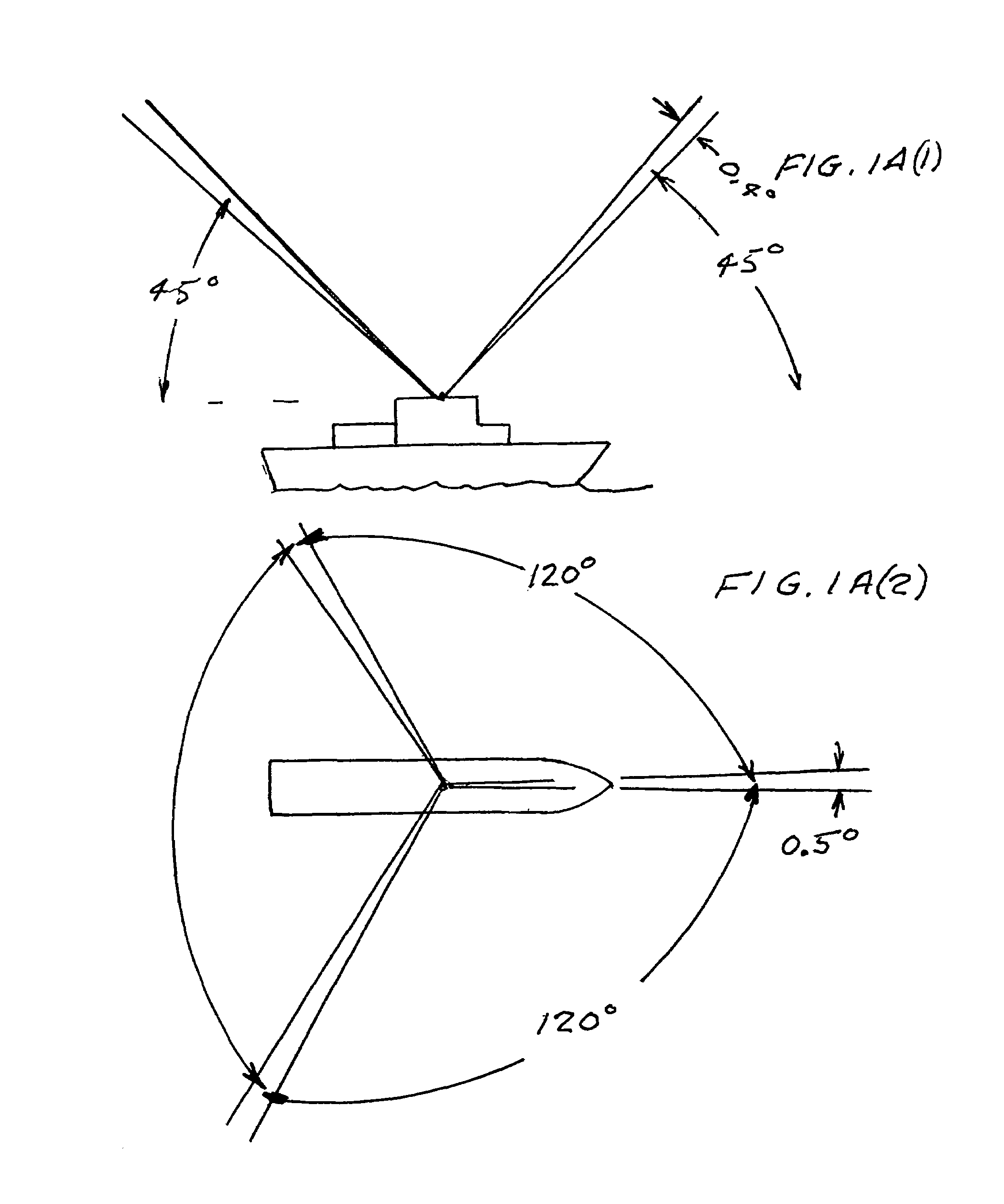
[0128]The first compact embodiment of the present invention uses a single telescope equipped with a two-axis high precision rotary stage to point the field of view at a selected bright infrared star within a search window. It also includes a temporary mirror which turns the telescope field of view by 90°. The latter is necessary because a geographical position determination requires that the star measurements be separated by an angular distance of between 90° and 120° in azimuth.

[0129]This design concept is shown in FIG. 17. When a temporary mirror 50 is inserted into the optical train, the field of view is deflected by 90°. A small telescope 52, nominally 5 cm aperture, points toward a mirror 54 mounted onto a precision stage 56 that has a 7.5° rotation capability, for example, the ARA125 from Aerotech, Inc. This rotary stage has an absolute accuracy of 1 arc-second. The telescope is fitted with an infrared camera to view stars within a field of view of nominally 0.44°×0.4°. The te...

second compact embodiment

[0131]The second compact embodiment of the present invention uses two identical telescopes mounted to a dual-axis precision rotary stage. In the design shown in FIG. 18, the two telescopes 60 and 62 are pointed at 90° with respect to each other, sharing a common focal plane. Small fold mirrors near the focal plane, not shown, are used to combine the fields of view onto one infrared camera. An alternate design would add a 45° fold mirror at the output of one of the telescopes, so that the two telescope bodies are essentially parallel, and the different fields of view are provided by the 45° fold mirror. A single infrared camera is used for both telescopes. Two approaches for combining two images in a single focal plane array have been described above and shown in FIG. 5B. This design also includes two temporary fold mirrors that can be inserted at a precise angle. These temporary mirrors increase the sky coverage for the cases where the solar angle is too close to the original direct...


PUM


Abstract

An automatic celestial navigation system for navigating both night and day by observation of K-band or H-band infrared light from multiple stars. In a first set of preferred embodiments three relatively large aperture telescopes are rigidly mounted on a movable platform such as a ship or airplane with each telescope being directed at a substantially different portion of sky. Embodiments in this first set tend to be relatively large and heavy, such as about one cubic meter and about 60 pounds. In a second set of preferred embodiments one or more smaller aperture telescopes are pivotably mounted on a movable platform such as a ship, airplane or missile so that the telescope or telescopes can be pivoted to point toward specific regions of the sky. Embodiments of this second set are mechanically more complicated than those of the first set, but are much smaller and lighter and are especially useful for guidance of aircraft and missiles. Telescope optics focus (on to a pixel array of a sensor) H-band or K-band light from one or more stars in the field of view of each telescope. Each system also includes an inclinometer, an accurate timing device and a computer processor having access to catalogued infrared star charts. The processor for each system is programmed with special algorithms to use image data from the infrared sensors, inclination information from the inclinometer, time information from the timing device and the catalogued star charts information to determine positions of the platform. Direction information from two stars is needed for locating the platform with respect to the celestial sphere. The computer is also preferably programmed to use this celestial position information to calculate latitude and longitude which may be displayed on a display device such as a monitor or used by a guidance control system. These embodiments are jam proof and insensitive to radio frequency interference. These systems provide efficient alternatives to GPS when GPS is unavailable and can be used for periodic augmentation of inertial navigation systems.

Description

[0001]This application claims the benefit of Provisional Application Ser. No. 60 / 619,858, filed Oct. 18, 2004 and is a Continuation In Part of Utility Application Ser. No. 11 / 106,744 filed Apr. 15, 2005.FIELD OF INVENTION[0002]This invention relates to stellar imaging systems and in particular to such systems useful for position location and platform attitude determination.BACKGROUND OF THE INVENTION[0003]Global positioning systems (GPS) are widely used for navigating ships and aircraft. However, these systems are vulnerable and have other shortcomings. Their space components are subject to hostile attack and the systems may be jammed. The systems also suffer from reliability failures and these GPS systems do not provide absolute azimuth positioning needed for attitude determination. Inertial navigation systems (INS) mitigate GPS deficiencies; however, these inertial navigation systems are not accurate over long time periods. Errors may accumulate at rates of about an arc-seconds pe...

Claims


Application Information

Patent Timeline
Patent Type & Authority Patents(United States)
IPC IPC(8): G21C21/00
CPCG01C21/025
Inventor BELENKII, MIKHAILBRUNS, DONALD G.RYE, VINCENT ABRINKLEY, TIMOTHY
Owner TREX ENTERPRISES CORP
Why Eureka
Try Eureka