
Insulating layer having decreased dielectric constant and increased hardness

a dielectric constant and insulating layer technology, applied in the field of insulating layers with decreased dielectric constants and increased hardness, can solve the problems of decreasing interconnect rc time constant delay, reducing line-to-line capacitance, and increasing difficulty, so as to increase the hardness increase the stability of the insulating layer, and improve the thermal stability

Inactive Publication Date: 2008-04-01
TAIWAN SEMICON MFG CO LTD
View PDF25 Cites 5 Cited by
  • Summary
  • Abstract
  • Description
  • Claims
  • Application Information

AI Technical Summary

Benefits of technology

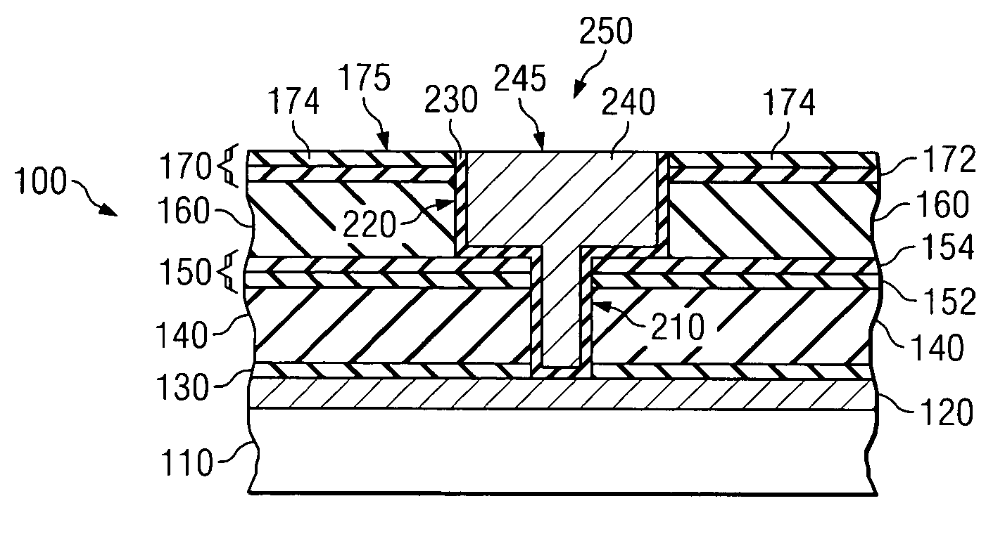
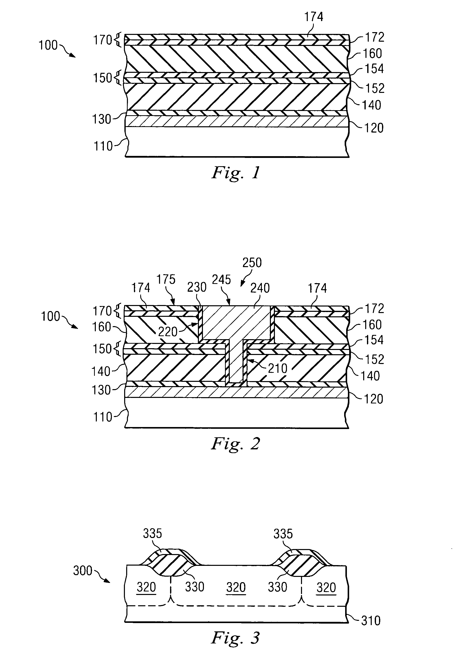
The present patent provides a method of manufacturing an insulating layer with improved mechanical strength and stability. This is achieved by forming a low-k dielectric layer on a substrate and then adding a carbon nitride cap layer on top, resulting in a second dielectric constant that is less than the first. The carbon nitride cap layer increases the hardness and stability of the insulating layer, while also increasing its density and reducing its susceptibility to moisture uptake. The patent also provides an integrated circuit device with this improved insulating layer and a semiconductor device with a landing yoke coated with carbon nitride.

Problems solved by technology

A challenge that has become ever more difficult as this scaling continues has been decreasing interconnect RC time constant delay.
Consequently, a reduction in line-to-line capacitance is one of the most critical issues for sub-0.25 μm devices.
However, low-k materials can exhibit a high porosity and low density, such that insulating layers comprising conventional low-k materials typically provide a film having insufficient hardness and excessive film stress.
Consequently, a stack of low-k dielectric films can suffer internal stress, due at least in part to lattice mismatches between over-stressed layers.
Moreover, such stress may intensify or build up during conventional fabrication procedures requiring substantial application forces and thermal cycling.
As a result, the low-k insulating layers may crack or peel, which can increase dielectric constants and decrease hardness values.
However, these processes provide only modest improvement in dielectric constants and insufficiently address on-going issues with excessive stress and insufficient mechanical stability.
For example, insulating layers undergoing such post treatment still experience dishing, cracking, pitting and peeling during chemical-mechanical polishing (CMP), and are highly susceptible to copper or other conductive material diffusion even after being annealed.

Method used


Image

  • Insulating layer having decreased dielectric constant and increased hardness
  • Insulating layer having decreased dielectric constant and increased hardness
  • Insulating layer having decreased dielectric constant and increased hardness

Examples


Embodiment Construction

[0017]It is to be understood that the following disclosure provides many different embodiments, or examples, for implementing different features of the invention. Specific examples of components and arrangements are described below to simplify the present disclosure. These are, of course, merely examples and are not intended to be limiting. In addition, the present disclosure may repeat reference numerals and / or letters in the various examples. This repetition is for the purpose of simplicity and clarity and does not in itself dictate a relationship between the various embodiments and / or configurations discussed. Moreover, the formation of a first feature over or on a second feature in the description that follows may include embodiments in which the first and second features are formed in direct contact, and may also include embodiments in which additional features may be formed interposing the first and second features, such that the first and second features may not be in direct ...


PUM

PropertyMeasurementUnit
thicknessaaaaaaaaaa
thicknessaaaaaaaaaa
feature sizesaaaaaaaaaa

Abstract

A method of manufacturing a mechanically robust insulating layer, including forming a low-k dielectric layer having a first dielectric constant on a substrate and forming a carbon nitride cap layer on the low-k dielectric layer, the insulating layer thereby having a second dielectric constant that is less than the first dielectric constant.

Description

BACKGROUND[0001]The present disclosure relates generally to semiconductor device insulating layers and, more specifically, to an insulating layer having a decreased dielectric constant and an increased hardness.[0002]Semiconductor device geometries continue to dramatically decrease in size. For example, existing semiconductor devices routinely include features having dimensions less than 90 nm. A challenge that has become ever more difficult as this scaling continues has been decreasing interconnect RC time constant delay. Those skilled in the art understand that power dissipation due to resistance-capacitance (RC) coupling becomes significant due to increased wiring capacitance, especially interline capacitance between the metal lines on the same metallization level. Smaller line dimensions increase the resistivity of the metal lines and the narrow spacing between the metal lines increases the resulting capacitance. Thus, device speed will increase as dimensions of ultralarge-scale...

Claims


Application Information

Patent Timeline
Patent Type & Authority Patents(United States)
IPC IPC(8): H01L23/58G02B6/35H01L21/312H01L21/314H01L21/316H01L21/318H01L21/768H01L23/532H01L29/51
CPCG02B6/3584H01L21/318H01L21/76832H01L23/53295H01L29/51G02B6/3518H01L21/3121H01L21/3122H01L21/3141H01L21/31612H01L21/31629H01L21/31633H01L21/76807H01L2924/0002H01L21/02118H01L2924/00H01L21/02123H01L21/02115H01L21/022H01L21/0228H01L21/02274H01L21/02271H01L21/02266H01L21/02362H01L21/02126H01L21/02164
Inventor CHANG, HUI LIN
Owner TAIWAN SEMICON MFG CO LTD
Learn More