Systems and methods for cleaning a chamber window of an EUV light source

a technology of euv light source and chamber window, which is applied in the direction of nuclear engineering, spectrometry/spectrophotometry/monochromator, optical radiation measurement, etc., can solve the problems of source material debris damage to the optical elements, damage or reduce the operational efficiency of the various plasma chamber optical elements, and the process of generating undesirable by-products, etc., to increase the rate of chemical reaction

Inactive Publication Date: 2008-04-08
ASML NETHERLANDS BV
View PDF165 Cites 21 Cited by
  • Summary
  • Abstract
  • Description
  • Claims
  • Application Information

AI Technical Summary

Benefits of technology

[0016]In another aspect of an embodiment, a cleaning system for a chamber window of an EUV light source, wherein the light source utilizes a plasma formation material and generates debris by plasma formation, may include an etchant source to introduce an etchant for the plasma formation material into the chamber. The cleaning system may also include a heating subsystem directing heated gas toward the window to heat deposited plasma formation material on a surface of the window to a temperature greater than 150° C. to increase a rate of a chemical reaction between deposited plasma formation material and the etchant.
[0017]In still another aspect, a cleaning system for a chamber window of a laser produced plasma EUV light source, wherein the light source utilizes a plasma formation material and generates debris by plasma formation may include a conical shroud that is positioned in the chamber and has a first end surrounding the window and a second open end. An etchant source may be provided to introduce an etchant for the plasma formation material into the shroud. Also, a heating subsystem may be provided to direct microwave radiation toward the window to heat deposited plasma formation material on a surface of the window to a temperature greater than 150° C. to increase a rate of a chemical reaction between deposited plasma formation material and the etchant.

Problems solved by technology

In addition to generating EUV radiation, these plasma processes also typically generate undesirable by-products in the plasma chamber which can include heat, high energy ions and scattered debris from the plasma formation, e.g., atoms and / or clumps / microdroplets of source material that is not fully ionized in the plasma formation process.
These plasma formation by-products can potentially damage or reduce the operational efficiency of the various plasma chamber optical elements including, but not limited to, collector mirrors including multi-layer mirrors (MLM's) capable of EUV reflection at normal incidence and grazing angle incident mirrors, the surfaces of metrology detectors, windows used to image the plasma formation process, and in the case of LPP, the laser input window.
The heat, high energy ions and / or source material debris may be damaging to the optical elements in a number of ways, including heating them, coating them with materials which reduce light transmission, penetrating into them and, e.g., damaging structural integrity and / or optical properties, e.g., the ability of a mirror to reflect light at such short wavelengths, corroding or eroding them and / or diffusing into them.
For these elements, deposits and heat can combine to fracture (i.e., crack) the element resulting in a loss of vacuum and requiring a costly repair.
Accessing contaminated or damaged optical elements in the plasma chamber for the purpose of cleaning or replacing the elements can be expensive, labor intensive and time-consuming.
In particular, these systems typically require a rather complicated and time consuming purging and vacuum pump-down of the plasma chamber prior to a re-start after the plasma chamber has been opened.
This lengthy process can adversely affect production schedules and decrease the overall efficiency of light sources for which it is typically desirable to operate with little or no downtime.

Method used


Image

  • Systems and methods for cleaning a chamber window of an EUV light source
  • Systems and methods for cleaning a chamber window of an EUV light source
  • Systems and methods for cleaning a chamber window of an EUV light source

Examples


Embodiment Construction

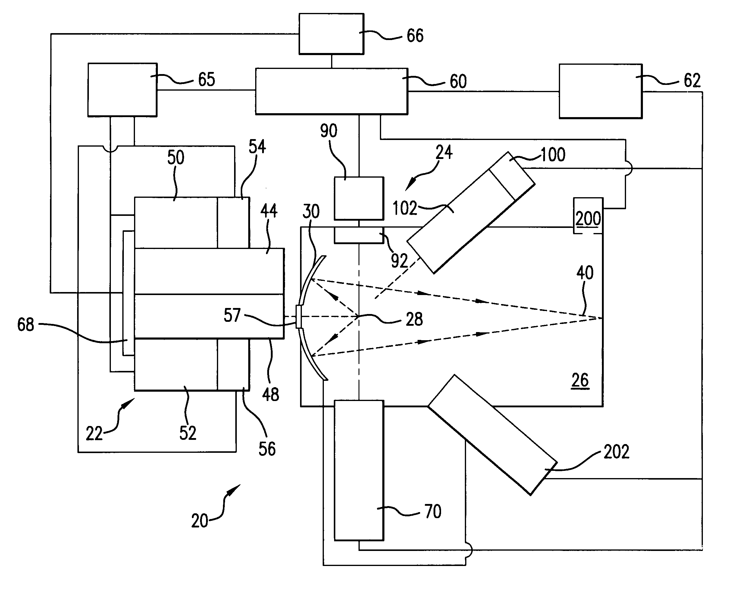
[0029]Turning now to FIG. 1 there is shown a schematic view of an exemplary production EUV light source, e.g., a laser produced plasma EUV light source 20 according to an aspect of the present invention. Although aspects of the present invention are illustrated with reference to a laser produced plasma (LPP), it is to be appreciated that certain aspects of the present invention may be equally applicable to other types of light sources which produce a plasma including an electric discharge produced plasma (“DPP”), a representative construction of which is disclosed in co-owned U.S. Pat. No. 6,815,700, which is hereby incorporated by reference.

[0030]Continuing with FIG. 1, an LPP light source 20 may contain a pulsed laser system 22, e.g., a gas discharge excimer or molecular fluorine laser operating at high power and high pulse repetition rate and may be a MOPA configured laser system, e.g., as shown in U.S. Pat. Nos. 6,625,191, 6,549,551, and 6,567,450. Depending on the application, ...


PUM


Abstract

Systems and methods are disclosed for cleaning a chamber window of an extreme ultraviolet (EUV) light source. The window may have an inside surface facing a chamber interior and an opposed outside surface and the light source may generate debris by plasma formation. For the system, a subsystem may be positioned outside the chamber and may be operable to pass energy through the window to heat debris accumulating on the inside surface of the window. In a first embodiment, the subsystem may place a flowing, heated gas in contact with the outside surface of the window. In another embodiment, electromagnetic radiation may be passed through the window.

Description

CROSS-REFERENCE TO RELATED APPLICATIONS[0001]The present application is a continuation-in-part application of U.S. patent application Ser. No. 11 / 174,442, entitled SYSTEMS AND METHODS FOR REDUCING THE INFLUENCE OF PLASMA-GENERATED DEBRIS ON THE INTERNAL COMPONENTS OF AN EUV LIGHT SOURCE, filed on Jun. 29, 2005, which is a continuation-in-part application of U.S. patent application Ser. No. 10 / 979,945, entitled LPP EUV LIGHT SOURCE, filed on Nov. 1, 2004, the disclosures of each of which are hereby incorporated by reference herein.[0002]The present application is also a continuation-in-part application of U.S. patent application Ser. No. 11 / 067,099, entitled SYSTEMS FOR PROTECTING COMPONENTS OF AN EUV LIGHT SOURCE FROM PLASMA-GENERATED DEBRIS, filed on Feb. 25, 2005, the disclosure of which is hereby incorporated by reference herein.[0003]The present invention is also related to U.S. patent application Ser. No. 10 / 900,839, entitled EUV LIGHT SOURCE, filed on Jul. 27, 2004, U.S. paten...

Claims


Application Information

Patent Timeline
Patent Type & Authority Patents(United States)
IPC IPC(8): G01J3/10
CPCB08B7/0071B82Y10/00G01N21/15G03F7/70916G03F7/70925G21K1/06H05G2/001G21K2201/061G21K2201/064G21K2201/067
Inventor BYKANOV, ALEXANDER N.MARX, WILLIAM F.
Owner ASML NETHERLANDS BV
Why Eureka
Try Eureka