Silicon carbide semiconductor device and method for manufacturing the same
a technology of silicon carbide and semiconductor devices, which is applied in the direction of semiconductor devices, semiconductor device details, electrical equipment, etc., can solve the problems of high input resistance of the gate, damage may remain, and the ion implanting apparatus with high energy is required, so as to improve the withstand voltage between the gate and the drain in the device, the gate input resistance becomes lower, and the effect of excellent electric properties
- Summary
- Abstract
- Description
- Claims
- Application Information
AI Technical Summary
Benefits of technology
Problems solved by technology
Method used
Image
Examples
first embodiment
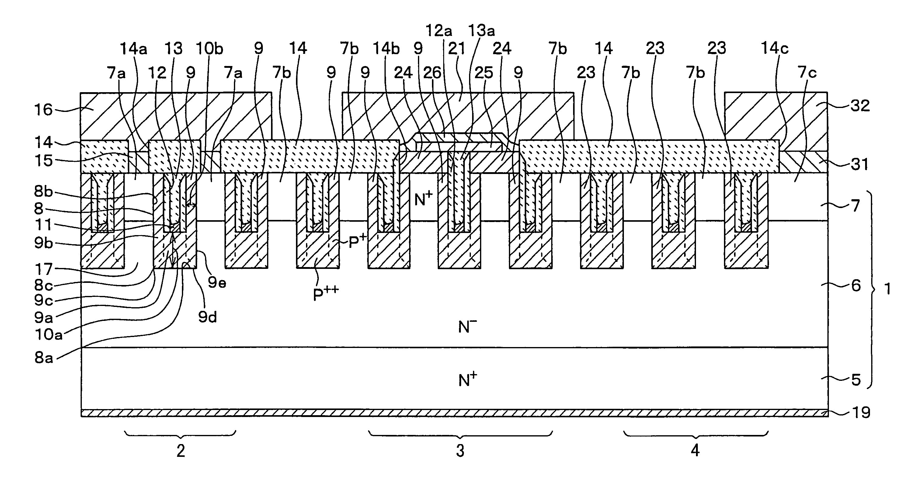
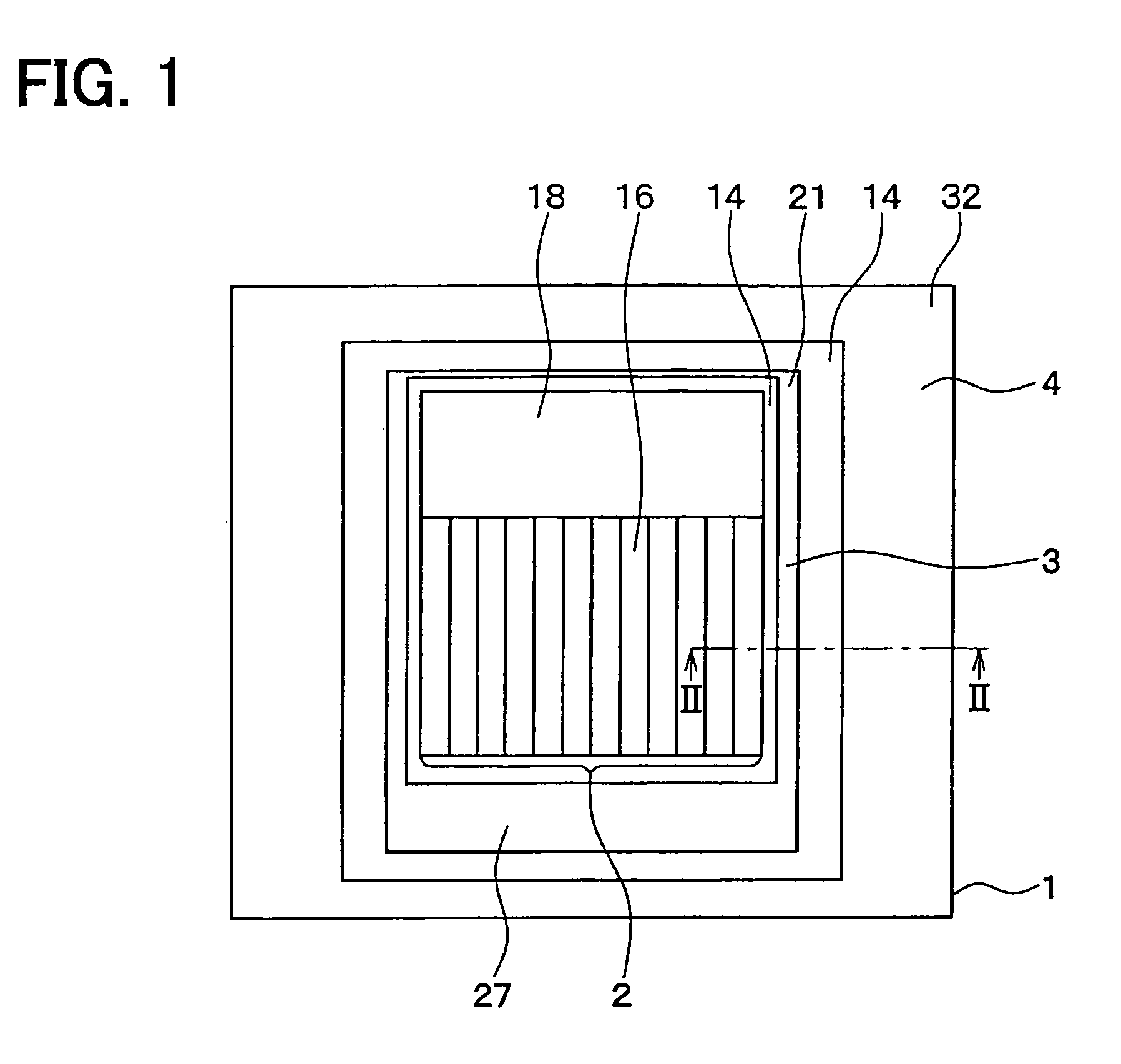
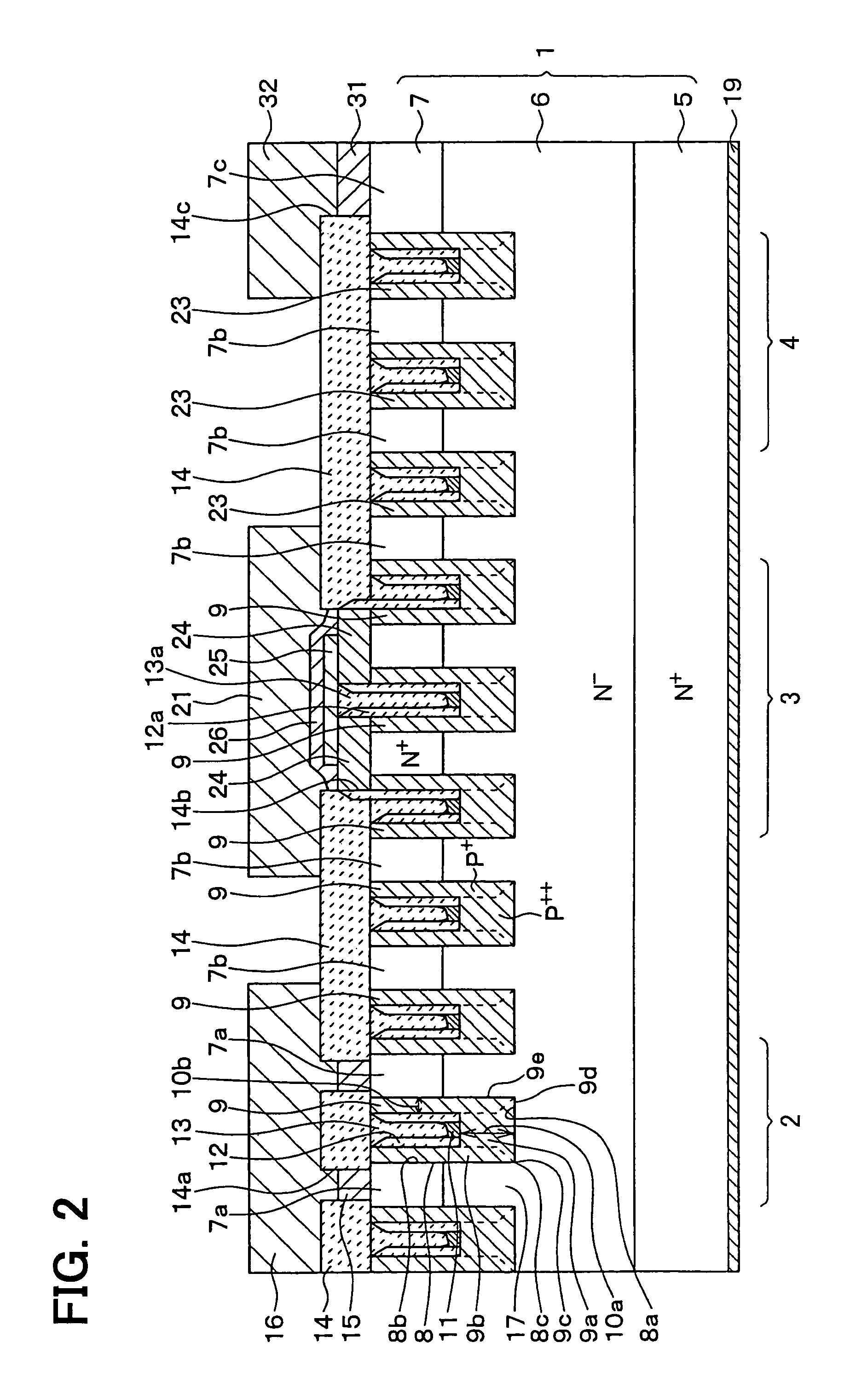
[0061]FIG. 1 is a plan view for showing a silicon carbide semiconductor device equipped with a JFET, according to a first embodiment mode of the present invention. Also, FIG. 2 is a cross sectional view for indicating the semiconductor device, taken along a line II-II shown in FIG. 1.
[0062]As represented in FIG. 1 and FIG. 2, the silicon carbide semiconductor device of this first embodiment mode has been equipped with a cell portion 2, a gate wiring portion 3, and an outer peripheral portion 4. The cell portion 2 is located at a center of a semiconductor substrate 1. The gate wiring portion 3 and the outer peripheral portion 4 are sequentially positioned on the outer peripheral side of this cell portion 2.
[0063]As illustrated in FIG. 2, in the semiconductor substrate 1, an N− type drift layer 6 and an N+ type semiconductor layer 7 functioning as a first semiconductor layer have been sequentially formed on a major surface of an N+ type substrate 5. In this first embodiment mode, a fi...
second embodiment
[0120]FIG. 17 is a plan view for indicating a silicon carbide semiconductor device according to a second embodiment mode of the present invention. FIG. 18 is a cross sectional view for showing the silicon carbide semiconductor device, taken along a line XVIII-XVIII of FIG. 17.
[0121]A major different point of the semiconductor device according to this second embodiment mode from the semiconductor device of the first embodiment mode is given as follows: That is, as represent in FIG. 17 and FIG. 18, both a body diode portion 51 and a floating P type layer region 52 are provided between the cell portion 2 and the outer peripheral portion 4 with respect to the semiconductor device according to the first embodiment mode.
[0122]In this second embodiment mode, as shown in FIG. 17, the body diode portion 51 has been arranged between the cell portion 2 and the gate wiring portion 3. Precisely speaking, two sets of the body diode portions 51 have been arranged in a region 651a which is differen...
third embodiment
[0157]FIG. 19 is a sectional view for indicating a silicon carbide semiconductor device according to a third embodiment mode of the present invention. In the first and second embodiment modes, the description has been made of such a case that the P type gate layer 9 having the U-shaped form has been formed in the cell portion 2. Alternatively, P type gate layers 9 can be formed by completely embedding P type semiconductor layers inside trenches 8. In other words, the shapes of the P type gate layers 9 can be alternatively made in such same shapes as the portions which have been removed by forming the trenches 8 in the semiconductor substrate 1 when the trenches 8 are formed in the semiconductor substrate 1.
[0158]Next, a method for manufacturing this silicon carbide semiconductor device will now be described. The manufacturing steps of the first embodiment mode are modified as follows: That is, in the step shown in FIG. 5, a P type semiconductor layer 41 formed on the surface of the ...
PUM
 Abstract
Description
Claims
Application Information
 - R&D
- Intellectual Property
- Life Sciences
- Materials
- Tech Scout
- Unparalleled Data Quality
- Higher Quality Content
- 60% Fewer Hallucinations
Browse by: Latest US Patents, China's latest patents, Technical Efficacy Thesaurus, Application Domain, Technology Topic, Popular Technical Reports.
© 2025 PatSnap. All rights reserved.Legal|Privacy policy|Modern Slavery Act Transparency Statement|Sitemap|About US| Contact US: help@patsnap.com


