
Process and apparatus for separation of hydrocarbons

a technology of hydrocarbon separation and process, which is applied in the direction of separation processes, lighting and heating apparatus, gaseous fuels, etc., can solve the problems of low efficiency of demethanizer or deethanizer reflux, low recovery ratio of ethane, and low liquid fraction of turbo-expander outlet stream, so as to achieve efficient hydrocarbon separation and reduce energy efficiency. the effect of efficiency

Active Publication Date: 2008-04-15
TOYO ENG CORP
View PDF32 Cites 26 Cited by
  • Summary
  • Abstract
  • Description
  • Claims
  • Application Information

AI Technical Summary

Benefits of technology

This approach enhances the recovery ratio of hydrocarbons like ethane and propane while maintaining energy efficiency by using all inlet gas for expansion and employing a high-concentration reflux, reducing the power required for compression and lowering operational costs.

Problems solved by technology

However, the liquid fraction of the outlet stream of the turbo-expander is low and effectiveness of refluxing in the demethanizer (or the deethanizer) is low; resultantly, the recovery ratio of ethane has remained at about 80%.
Moreover, in these arts, since a liquid low in methane (or ethane) concentration is used as a principal reflux, effectiveness of the refluxing is not excellent.
Consequently, power for compressing the residue gas increases, and energy efficiency of the whole apparatus inevitably declines.

Method used


Image

  • Process and apparatus for separation of hydrocarbons
  • Process and apparatus for separation of hydrocarbons

Examples


example 1

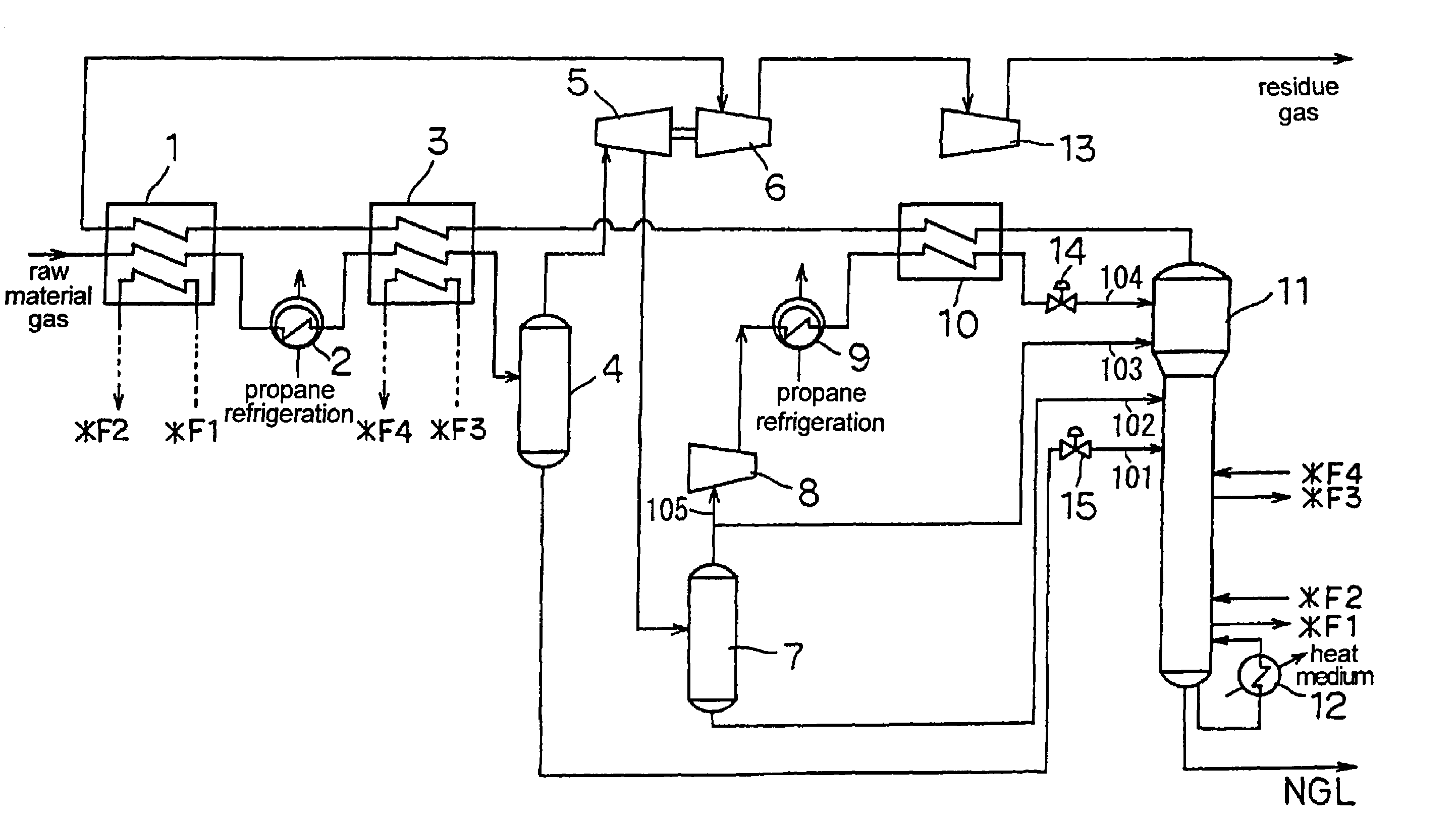
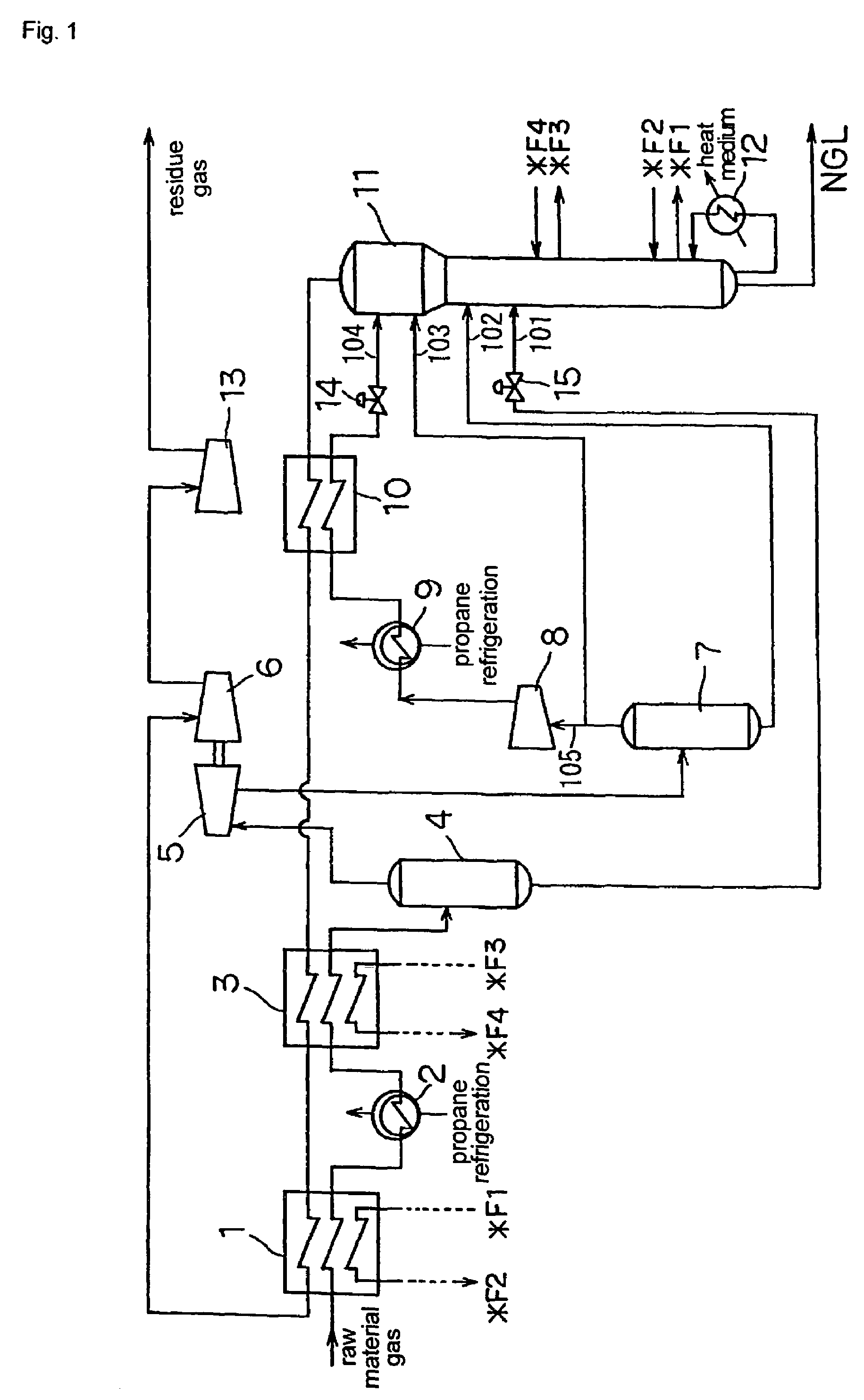
[0080]There is described a case in which ethane recovery was conducted using a gas-processing plant constituted as shown in FIG. 1. However, the present invention is in no way restricted thereto. Here, a high-pressure feed natural gas, from which water has been removed beforehand, is introduced into the gas-processing plant under the conditions of 6.24 MPa and 17.1° C. The composition of the feed gas is shown in Table 1. The flow rate is 13,700 kg-mol / hour (103 mol / hour). Incidentally, Cn (n is a natural number) refers to a hydrocarbon of which carbon number is n. C5+ refers to hydrocarbons of which carbon number is 5 or more.

[0081]

TABLE 1Composition of feed gas (mole %)CO21.00N20.54C189.41C24.91C32.23C41.29C5+0.62Total100.00

[0082]The feed gas is cooled to −29° C. in first feed gas cooler 1 by heat exchange with a residue gas of −39.7° C. and a side stream of demethanizer 11 of −23.3° C. Then, the gas is cooled to −37° C. in feed gas chiller 2 by propane refrigeration and to −51.5° ...


PUM

PropertyMeasurementUnit
temperatureaaaaaaaaaa
outlet pressureaaaaaaaaaa

Abstract

There are provided a process for separation of hydrocarbons including the steps of: (a) a feed gas is cooled and partly condensed, and separated into a gas and a liquid; (b) the liquid obtained in step (a) is supplied to a distillation column; (c) the gas obtained in step (a) is expanded by an expander and partly condensed, and separated into a gas and a liquid; (d) the liquid obtained in step (c) is supplied to the distillation column; (e) the gas obtained in step (c) is divided into a first portion and a second portion; (f) the first portion is supplied to the distillation column; (g) the second portion is condensed by being compressed and cooled, and then depressurized and supplied as a reflux to the distillation column; and (h) a residue gas is obtained from the top part of the distillation column and a heavier fraction is obtained from the bottom part of the distillation column; and an apparatus therefor. The process and apparatus enable efficient separation of hydrocarbons.

Description

TECHNICAL FIELD[0001]The present invention relates to a process and an apparatus for separation of hydrocarbons, both used for separating and recovering ethane or propane from, for example, a natural gas, an associated gas from an oil reserver, or an off-gas from a refinery or a petrochemical plant.BACKGROUND ART[0002]It has been conducted to separate methane from hydrocarbons having 2 or more carbon atoms, or ethane from hydrocarbons having 3 or more carbon atoms.[0003]For example, as a process for recovering ethane or propane from a natural gas, there is in wide use a process in which a natural gas is cooled and then distillated in a demethanizer (a deethanizer in the case of propane recovery) to separate lighter components from ethane (or propane) and heavier hydrocarbon components. In the process, there is used a propane refrigeration system and a turbo-expander in order to cool the natural gas down to a temperature necessary for the separation. However, the liquid fraction of t...

Claims


Application Information

Patent Timeline
Patent Type & Authority Patents(United States)
IPC IPC(8): F25J3/00C10G5/06F25J3/02
CPCB01D53/002C10G5/06C10L3/10F25J3/0209F25J3/0233F25J3/0238F25J2270/60F25J2200/02F25J2200/70F25J2205/04F25J2230/08F25J2230/60F25J2240/02F25J2270/12B01D2257/702
Inventor OHARA, SUSUMUYAMAGUCHI, SHOICHIYAMAMORI, YASUYUKIEVELYNE, JAHJA
Owner TOYO ENG CORP
Learn More