Threaded joint for steel pipes

Active Publication Date: 2008-04-22
NIPPON STEEL CORP +1
View PDF40 Cites 24 Cited by
  • Summary
  • Abstract
  • Description
  • Claims
  • Application Information

AI Technical Summary

Benefits of technology

[0026]A coating formed by dispersing wax particles in a lubricating oil is normally in the form of liquid or semi-solid at room temperature, and it may be as greasy as the lubricating oil, so foreign matter may tend to adhere thereto. In contrast, a coating of a mixture comprising a lubricating oil and a wax formed by heating the mixture so as to cause the oil and wax to dissolve in each other is in the form of solid or semi-solid at room temperature, which is less greasy or has a dry touch, and it is difficult for foreign matter to adhere thereto. However, during fastening or loosening of the threaded joint, the wax melts immediately by the generated frictional heat so that the entire coating is liquefied. Accordingly, the same self-repairing function as obtained with a liquid lubricant can be attained, and good anti-galling properties are exhibited.
[0027]In the second embodiment, the process of manufacturing a threaded joint is simpler compared to

Problems solved by technology

However, in order to attain a high level of lubricity which is sufficient to provide such anti-galling properties to a metal-to-metal seal portion, it is necessary to include a large amount

Method used


Image

  • Threaded joint for steel pipes
  • Threaded joint for steel pipes

Examples


Example

Example 1

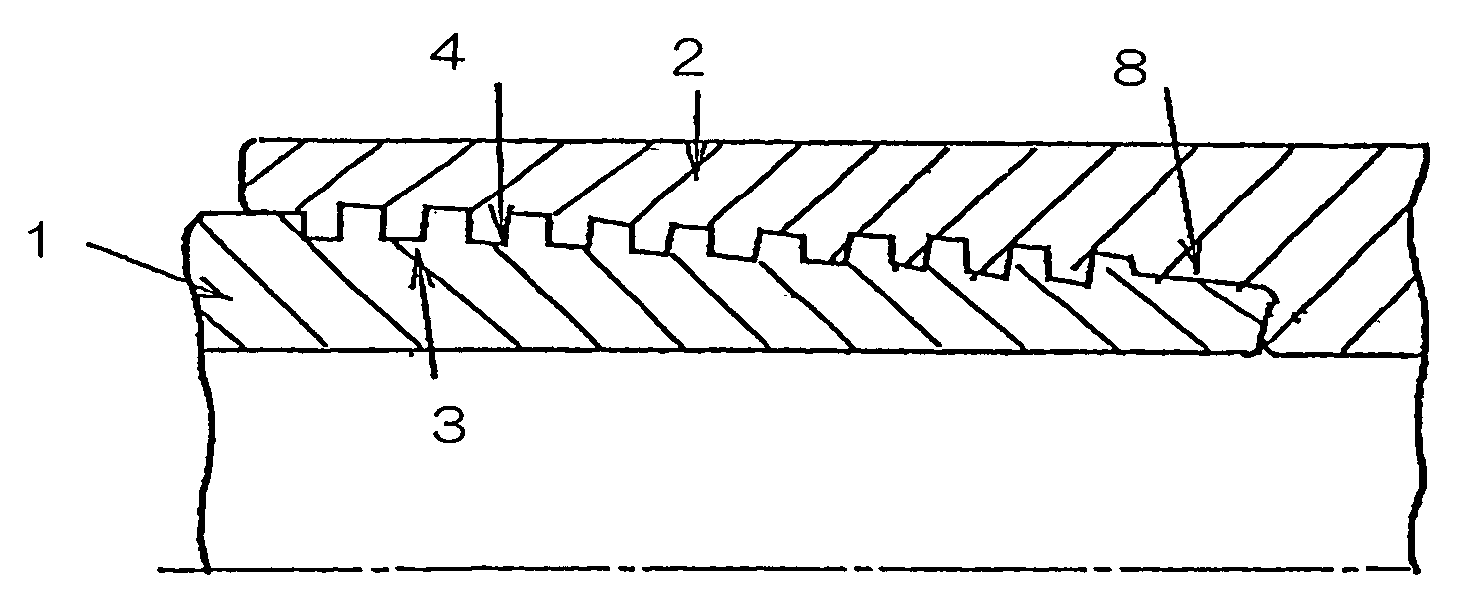
[0087]This example illustrates a threaded joint made of a 13Cr steel having a lubricating coating comprising a lower liquid layer and an upper solid layer formed on the box surface of the joint in accordance with the first embodiment of the present invention.

[0088]The pin surface of the joint remained untreated.

[0089]The box surface was preliminarily treated by shot blasting, and within one hour therefrom, it was coated with a lubricating coating having a liquid layer and a solid layer in the manner summarized in Table 1.

[0090]In Table 1, the viscosity of the material for a liquid layer is the value measured at 40° C. In the case of a liquid layer made of a basic metal salt of an organic acid (Ba or Ca sulfonate), it was used for application after dilution with a volatile solvent (xylene). In the case of a solid layer made of a mica powder, the powder was dispersed in a nitrocellulose solution, which was applied by spraying. The applied layer did not intermingle with the lo...

Example

Example 2

[0098]This example illustrates a threaded joint made of a 13Cr steel or a carbon steel having a lubricating coating of a mixture comprising a lubricating oil and a wax formed on the box surface of the joint in accordance with the second embodiment of the present invention.

[0099]The pin surface of the joint, to which a lubricating coating was not applied, was subjected to preliminary surface treatment, which was chemical conversion treatment with manganese phosphate for a pin made of a carbon steel, or copper plating for a pin made of a 13Cr steel.

[0100]The box surface was preliminarily treated in the same manner as in Example 1 (by shot blasting), and within one hour therefrom, it was coated with a lubricating coating of a mixture comprising a lubricating oil, wax, and optionally a solid additive in the manner summarized in Table 3. The application of the mixture was performed either after the mixture had been heated to liquefy the mixture (liquefy the wax) or after it had ...


PUM


Abstract

A threaded joint for steel pipes comprising a pin 1 and a box 2 each having a contact surface comprising a threaded portion 3 or 4 and an unthreaded metal contact portion 8 is provided with improved anti-galling propertied by forming a lubricating coating on the contact surface of at least one of the pin and the box, the lubricating coating exhibiting a self-repairing function by liquid lubrication and having a decreased greasiness. The lubricating coating is (1) a coating which comprises a lower lubricant layer which is in liquid form in the temperature range of above 0° C. and below 40° C. and an upper lubricant layer which is in solid form at 40° C., or (2) a coating which is semi-solid or solid at 40° C. and is formed of a mixture comprising a lubricating oil which is in liquid form in the temperature range of above 0° C. and below 40° C. and a wax which is in solid form at 40° C., the mixture preferably having been heated so as to liquefy the wax and dissolve in each other the wax and lubricant oil.

Description

[0001]This application is a continuation of International Patent Application No. PCT / JP03 / 06743, filed May 29, 2003. This PCT application was not in English as published under PCI Article 21(2).TECHNICAL FIELD[0002]This invention relates to a threaded joint for steel pipes having a lubricating coating on the surface thereof and particularly to such a threaded joint in which the lubricating coating provides the threaded joint with improved galling resistance so as to make it possible to fasten and loosen the joint repeatedly, with the coating having a decreased greasiness to minimize the tendency for foreign matter to adhere to the coating.BACKGROUND ART[0003]Oil well pipes such as tubing and casing used in the drilling of oil or gas wells are typically connected to each other by threaded joints. In the past, the depth of oil wells was typically 2000 to 3000 meters, but more recently, the depth of oil wells may reach 8,000 to 10,000 meters in offshore oil fields and other deep wells....

Claims


Application Information

Patent Timeline
IPC IPC(8): F16L15/00C10M159/06F16L15/04C10M177/00F16L15/06
CPCC10M177/00E21B17/042F16L58/182F16L15/004Y10T428/1393C10M2201/0623C10M2201/103C10M2201/1033C10M2203/10C10M2203/1006C10M2205/16C10M2207/0285C10M2207/2623C10M2207/281C10M2207/2815C10M2219/046C10M2219/0463C10N2240/22C10N2250/10C10N2250/14C10M2201/062C10N2040/34C10N2050/023C10N2050/10
Inventor MATSUMOTO, KEISHIGOTO, KUNIOANRAKU, TOSHIRONAGASAKU, SHIGEOYAMAMOTO, HIDEO
Owner NIPPON STEEL CORP
Why Eureka
Try Eureka