Method of logic circuit synthesis and design using a dynamic circuit library

a dynamic circuit and logic circuit technology, applied in the field of logic circuit synthesis and design, can solve the problems of complex logic circuitry, complicated logic operation, and large complexity of optimization problems which must be performed, and achieve the effect of simplifying the logic synthesis step, improving the overall performance of the desired logic circuit, and being easy to constru

Inactive Publication Date: 2008-04-22
GLOBALFOUNDRIES INC
View PDF20 Cites 2 Cited by
  • Summary
  • Abstract
  • Description
  • Claims
  • Application Information

AI Technical Summary

Benefits of technology

[0007]It is an object of the invention to provide a logic circuit design method which employs simplified logic synthesis. Another object of the invention is to provide a method of logic synthesis which utilizes a dynamic circuit library to simplify the optimization problem which the tool must solve and thereby reduce the processing time required for logic synthesis.
[0010]The method according to the invention allows the circuit designer to take advantage of dynamic logic circuitry to improve overall performance of the desired logic circuit. The resulting delayed-reset dynamic logic circuit having a fixed number of reset levels is relatively easy to construct and ensure proper operation as compared to generic dynamic circuits. Perhaps most importantly, limiting the logic synthesis step to a circuit library consisting of a single logic circuit greatly simplifies the logic synthesis step. The remaining steps to finalize the circuit design, that is, the steps of eliminating unnecessary or unused devices in the synthesized intermediate circuit and then sizing the devices in the final circuit, are straightforward tasks which can be done manually or by some automated means.

Problems solved by technology

In many cases the logical operations may be very complicated and require complicated logic circuitry.
Thus, logic synthesis comprises an optimization problem constrained by the library of available circuits available for synthesis, by the required logical operation to be performed by the final circuit, and perhaps by other constraints dictated by the designer.
However, this flexibility comes at the cost of vastly increasing the complexity of the optimization problem which must be performed.
This increase in complexity results in an increase in the processing time which the synthesis tool requires in order to produce a solution.
Another problem associated with prior static circuit logic synthesis involves the timing performance of the synthesized circuit.
Where the logic synthesis tool is not constrained by timing considerations, a constraint that further complicates the optimization problem to be performed, the timing associated with synthesized circuit may be unpredictable.
The unpredictable timing associated with the synthesized static logic circuit may make the circuit difficult to use with other components of an overall system.

Method used


Image

  • Method of logic circuit synthesis and design using a dynamic circuit library
  • Method of logic circuit synthesis and design using a dynamic circuit library
  • Method of logic circuit synthesis and design using a dynamic circuit library

Examples


Embodiment Construction

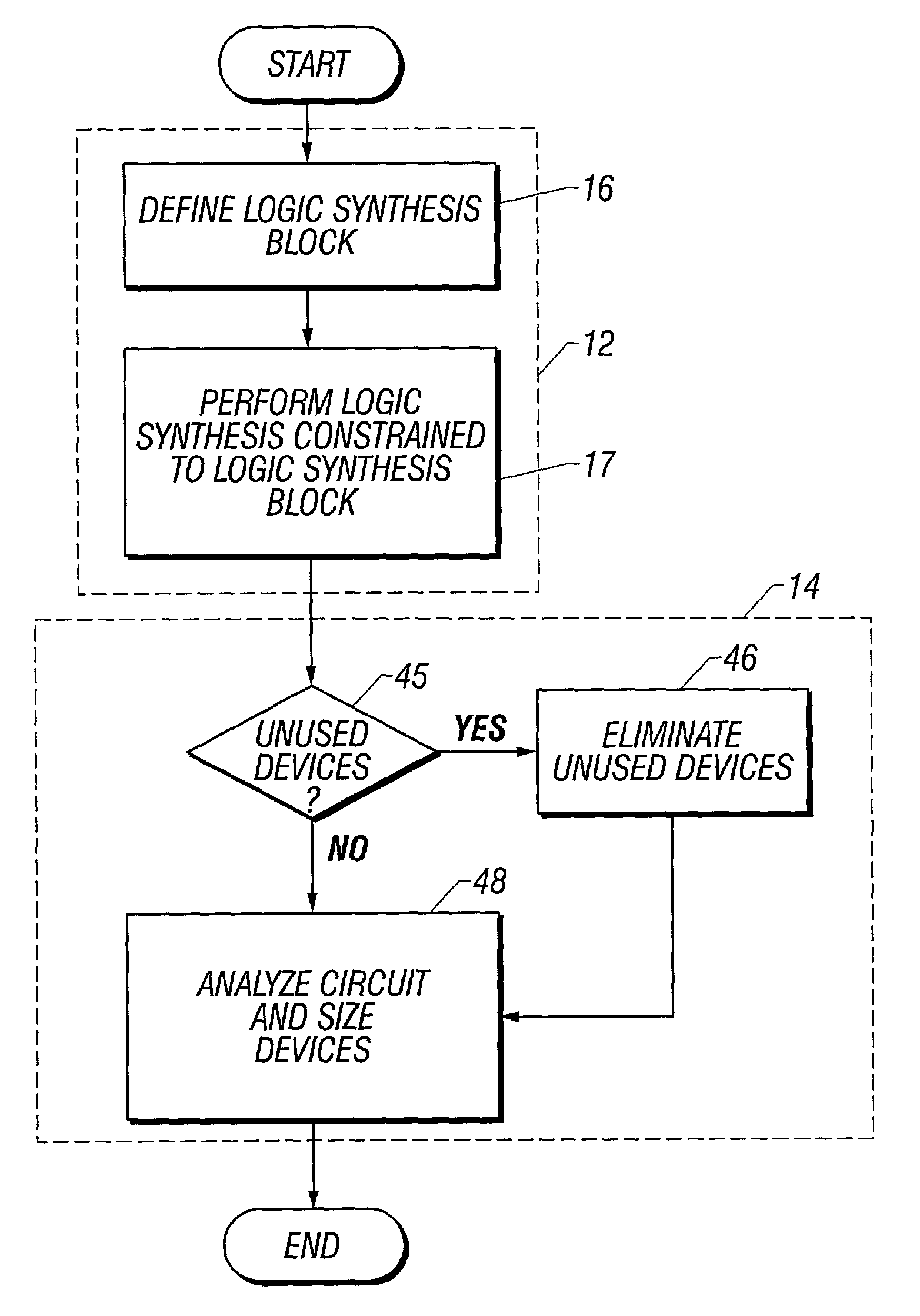
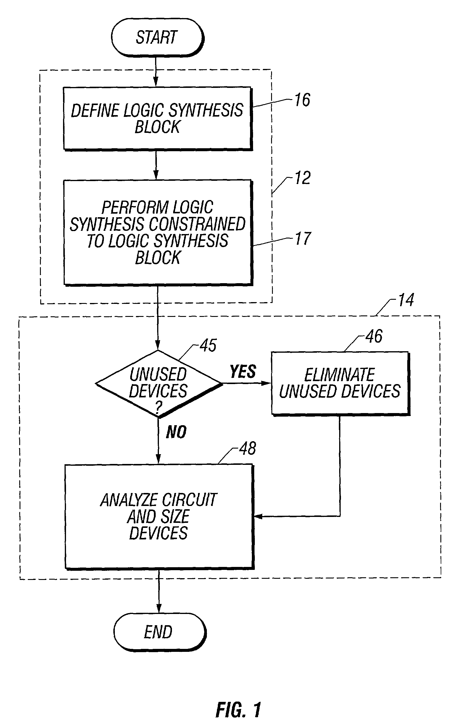
[0018]FIG. 1 illustrates the process steps included in a logic circuit design process embodying the principles of the invention. The design process involves a logic synthesis component shown in dashed box 12 and a design component shown in dashed box 14. Steps in logic synthesis component 12 produce an intermediate logic circuit design, described below with reference to FIG. 4, which performs a desired logical operation. Steps in design component 14 use this intermediate logic circuit design to provide an efficient final logic circuit for performing the desired logical operation.

[0019]The process starts with the designer providing or defining the high level logical operation to be performed by the circuit. According to the invention, logic synthesis component 12 includes first defining a logic synthesis block as shown at process block 16. The process next includes performing logic synthesis as shown at process block 17 to produce the intermediate circuit capable of performing the pr...


PUM


Abstract

The circuit library available for logic synthesis is limited to a single dynamic circuit block or logic synthesis block. The circuit design method includes first defining the logic synthesis block (16) and then performing logic synthesis (17) for a predetermined logical operation to be implemented. The logic synthesis step constrained to the single logic synthesis block produces an intermediate circuit design (29) which necessarily comprises a series of dynamic circuit blocks, each associated with a single reset signal. Once the intermediate circuit (29) is produced, the circuit design method includes eliminating unnecessary devices (46) from the intermediate circuit (29) to produce a final logic circuit, and then sizing the devices (48) in the final circuit to complete the design.

Description

TECHNICAL FIELD OF THE INVENTION[0001]This invention relates to the design of digital logic circuits. More particularly, the invention relates to a method for synthesizing logic circuits from high-level logic representations.BACKGROUND OF THE INVENTION[0002]Logic circuits are electronic circuits that perform some logical operation or group of logical operations on a set of digital input data to provide some desired digital output. For example, a simple logic circuit may perform an AND operation on input data comprising three logic level signals to provide a single output comprising the logical signal resulting from the AND operation. These types of logic circuits are included in many different types of devices from control circuits for mechanical devices, to communications devices, to data processor chips. In many cases the logical operations may be very complicated and require complicated logic circuitry.[0003]Logic circuit design involves first determining the particular logical f...

Claims


Application Information

Patent Timeline
Patent Type & Authority Patents(United States)
IPC IPC(8): G06F17/50
CPCG06F17/505G06F30/327
Inventor DHONG, SANG HOOHOFSTEE, HARM PETERPOSLUSZNY, STEPHEN DOUGLASSILBERMAN, JOEL ABRAHAMTAKAHASHI, OSAMUWENDEL, DIETER F.
Owner GLOBALFOUNDRIES INC
Why Eureka
Try Eureka