Gas turbine power plant and method of operating the same

a gas turbine power plant and gas turbine technology, applied in the direction of machines/engines, energy input, oxygen/ozone/oxide/hydroxide, etc., can solve the problems of reducing the performance of the plant, consuming a large amount of energy, and penalizing the efficiency and power output of the plant, so as to increase the overall efficiency of the power plant

Inactive Publication Date: 2008-04-29
GENERAL ELECTRIC TECH GMBH
View PDF9 Cites 112 Cited by
  • Summary
  • Abstract
  • Description
  • Claims
  • Application Information

AI Technical Summary

Benefits of technology

[0004]The present invention relates to providing a method of operating a gas turbine power plant and a gas turbine power plant which avoid disadvantages of the prior as well as increasing the overall efficiency of the power plant.
[0007]Optionally, prior to entering the membrane reactor, the air stream from the compressor can be lead to a catalytic burner where the air is heated by means of catalytic combustion. The fuel for the catalyst is either hydrogen or natural gas. Thereby the use of hydrogen is preferred to avoid producing CO2. The reason for using a catalytic burner is to increase the average temperature in the membrane / POX reactor thereby increasing the oxygen flux through the membrane. Also, the temperature gradient in the reactor will be lower and thus the thermal stresses for the reactor will decrease.
[0008]Advantageously the syngas coming from the membrane / POX reactor consisting of hot steam, H2 and CO can enter a low temperature heat exchanger, where the syngas mixture is cooled down by an incoming stream of the compressed air from the compressor. Another possibility would be to use a medium temperature heat exchanger to raise the temperature of the mixture of steam and natural gas before the mixture enters the membrane / POX reactor. This would flatten out the temperature profile in the membrane / POX reactor and thus lower the temperature gradients in this.

Problems solved by technology

One major disadvantage of using air-separation units for these kind of processes is that they consume a great amount of energy, thus penalizing the efficiency and power output of the plant.
Also this technique has a few disadvantages, namely: metal to ceramic sealing is needed that can withstand temperatures >800° C., the turbine inlet temperature (TIT) and the ceramic sealing temperature are linked, which limits the maximum TIT and thus lowers the performance of the plant and one needs to separate large amounts of air, corresponding to the total O2 required for full oxidation of fossil fuel powering the gas turbine.

Method used


Image

  • Gas turbine power plant and method of operating the same
  • Gas turbine power plant and method of operating the same
  • Gas turbine power plant and method of operating the same

Examples


Embodiment Construction

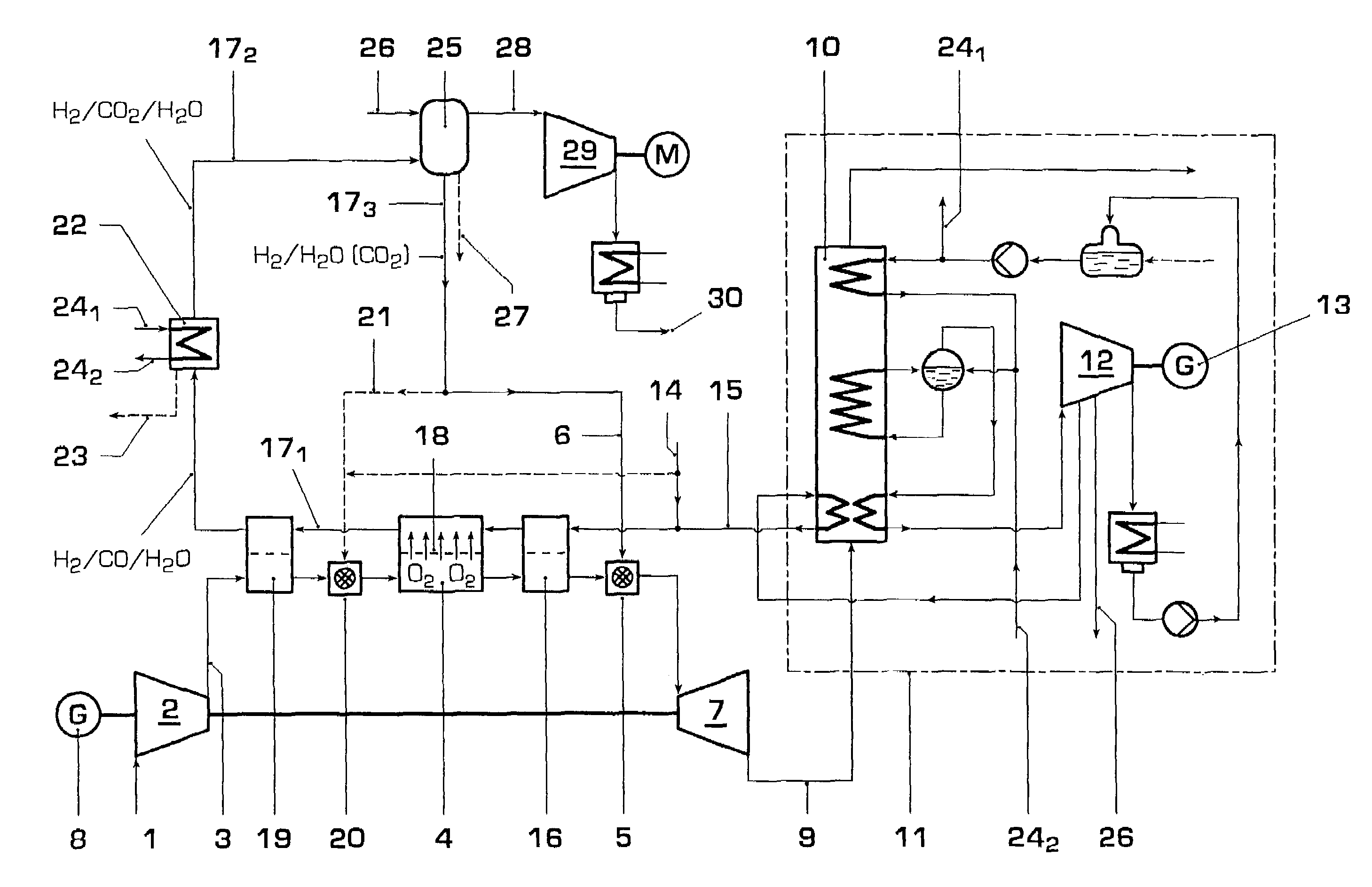
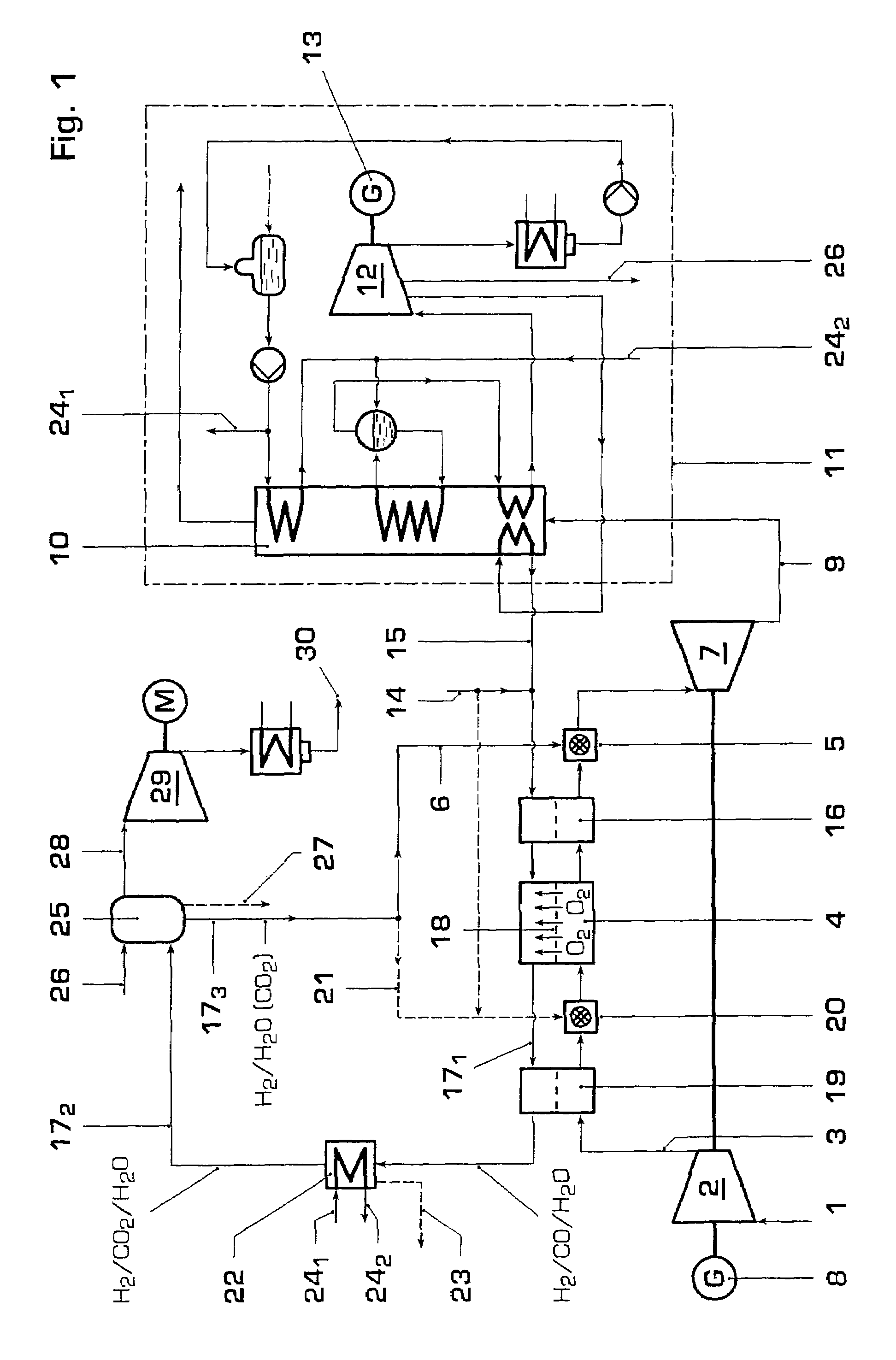
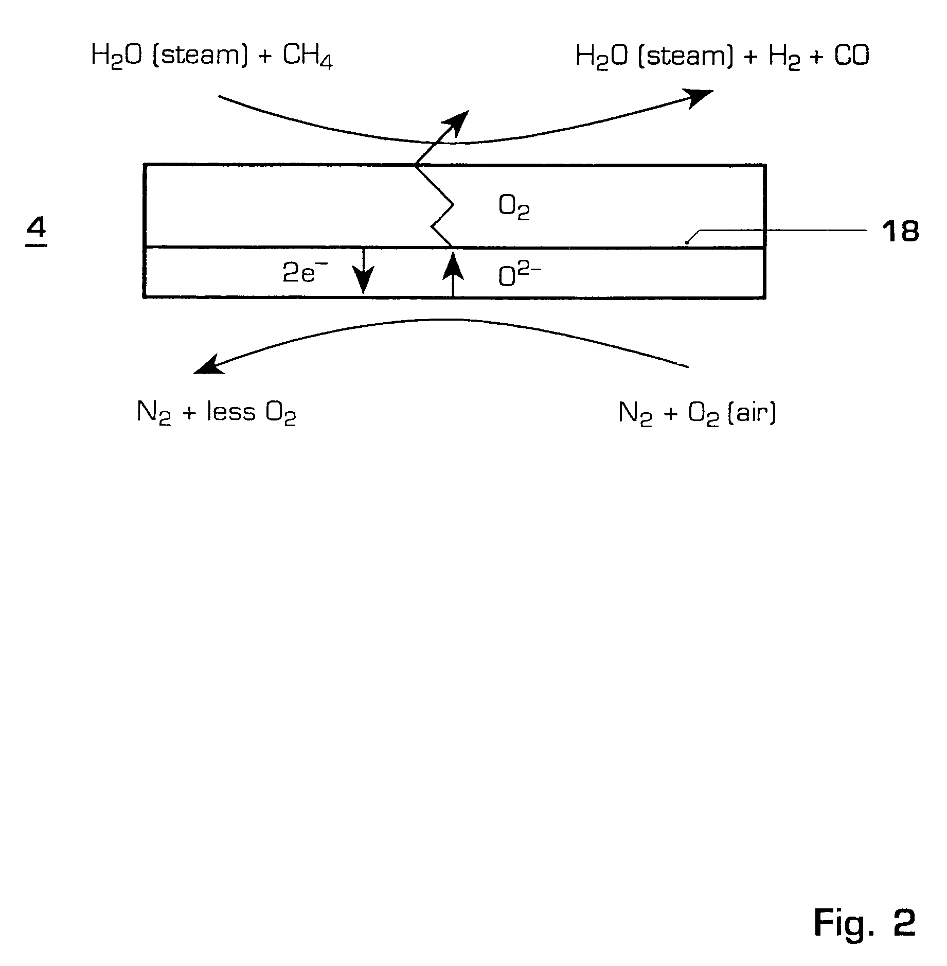
[0014]FIG. 1 shows a syngas based low emission power plant according to the present invention. Air 1 is fed through a compressor 2 before the compressed air 3 is fed at least through a membrane / partial oxidation (POX) reactor 4. After the membrane / POX reactor 4 the air is burned in a combustion chamber 5 together with hydrogen 6. The flue gases are then expanded in a turbine 7, which is driving the compressor 2 and producing electricity in a generator 8. After the expansion the hot flue gases 9 are utilised in a heat recovery steam generator 10 producing steam for the bottoming steam cycle 11 and producing more power in a steam turbine 12 and electricity in a generator 13.

[0015]As can be seen from FIG. 1, natural gas 14 is being mixed with superheated intermediate pressure steam 15 and is then lead to the membrane / POX reactor 4. One possibility here would be to use a medium temperature beat exchanger 16 to raise the temperature of the mixture of steam 15 and natural gas 14. This wou...


PUM


Abstract

A method of operating a gas turbine power plant and gas turbine power plant are disclosed wherein hydrogen for the combusting process is produced by feeding natural gas mixed with steam through a membrane / partial oxidation reactor and converting the natural gas at least to H2 and CO. Thereby oxygen is transferred from the compressed air through the membrane of the membrane / partial oxidation reactor and the oxygen is used for the partial oxidation process of the natural gas. The process is followed by converting the syngas in a CO shift reactor and a CO shift reactor to a CO2 removal equipment to mainly hydrogen.

Description

CROSS-REFERENCE TO RELATED APPLICATIONS[0001]This application is a continuation of the U.S. National Stage designation of co-pending International Patent Application PCT / EP2003 / 050782 filed Nov. 3, 2003, which claims priority to U.S. provisional application No. 60 / 424,681 filed Nov. 8, 2002 and European patent application no. 02405995.8 filed Nov. 19, 2002, and the entire contents of these applications are expressly incorporated herein by reference thereto.FIELD OF THE INVENTION[0002]The invention relates to a method of operating a gas turbine power plant and a gas turbine power plant.BACKGROUND OF THE INVENTION[0003]In the last years different projects were launched with the aim to develop emission free gas turbine based processes using semi-closed cycles with CO2 / H2O mixtures as working fluid. Methods of operating such power plants are known for example from EP-A1-0 939 199 and EP-A1-0 953 748. In these processes the fuel, usually natural gas, reacts with technically pure oxygen g...

Claims


Application Information

Patent Timeline
Patent Type & Authority Patents(United States)
IPC IPC(8): F02C3/20F01K23/10F02C3/22F02C3/30F02C6/18
CPCF01K23/10F02C3/22F02C3/30F02C6/18C01B3/386C01B3/48C01B13/0251C01B2203/0261C01B2203/0283C01B2203/0475C01B2203/0827C01B2203/0883C01B2203/84C01B2203/86Y02P20/129Y02P30/00
Inventor GRIFFIN, TIMOTHYHOLMBERG, DANIELWINKLER, DIETER
Owner GENERAL ELECTRIC TECH GMBH
Why Eureka
Try Eureka