Supercharge Your Innovation With Domain-Expert AI Agents!

Impedance-matched IQ network for an image rejection circuit

a technology of image rejection circuit and iq network, which is applied in the field of radio frequency communication systems, can solve the problems of degrading network performance, reducing signal strength and noise figure, and introducing gain and phase mismatch, and reducing network performance, so as to reduce noise, reduce signal loss, and reduce distortion

Inactive Publication Date: 2008-05-06
ENTROPIC COMM INC
View PDF6 Cites 8 Cited by
  • Summary
  • Abstract
  • Description
  • Claims
  • Application Information

AI Technical Summary

Benefits of technology

[0007]The present invention provides an impedance-matched IQ network which allows the image rejection circuit to operate with lower signal losses, lower noise, and lower distortion for improved performance. Additionally, the circuit elements of the IQ network may, but not necessarily, be configured to function as the biasing circuitry for the connecting mixers.

Problems solved by technology

The implementation suffers some disadvantageous, however, in that the resistor elements of the phase shifter degrade signal strength and noise figure.
Additionally, the non-linearity and noise of the buffer amplifiers 202 and 204 further degrade the network's performance.
In addition, variation in buffer gain and in the RCA components introduce gain and phase mismatch.
This architecture suffers drawbacks such as complexity in its fabrication and biasing, degraded noise figure, and higher non-linearity, due to the implementation of additional mixers 222 and 224.

Method used


Image

  • Impedance-matched IQ network for an image rejection circuit
  • Impedance-matched IQ network for an image rejection circuit
  • Impedance-matched IQ network for an image rejection circuit

Examples


Embodiment Construction

[0020]The present invention provides an impedance-matched IQ network for use in an image rejection circuit. As familiar to those skilled in the art of high frequency systems, impedance-matched systems exhibit lower signal loss compared to unmatched systems due to the reduction / elimination of impedance discontinuities. Also, impedance matching is preferred in order to obtain the appropriate performance from the following IF stage; typically an IF filter.

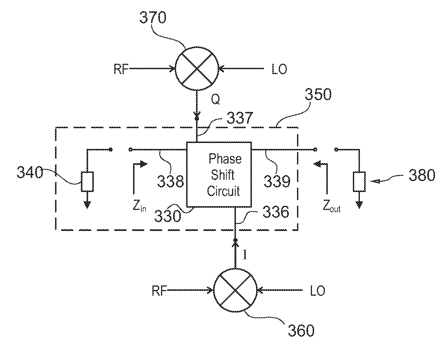
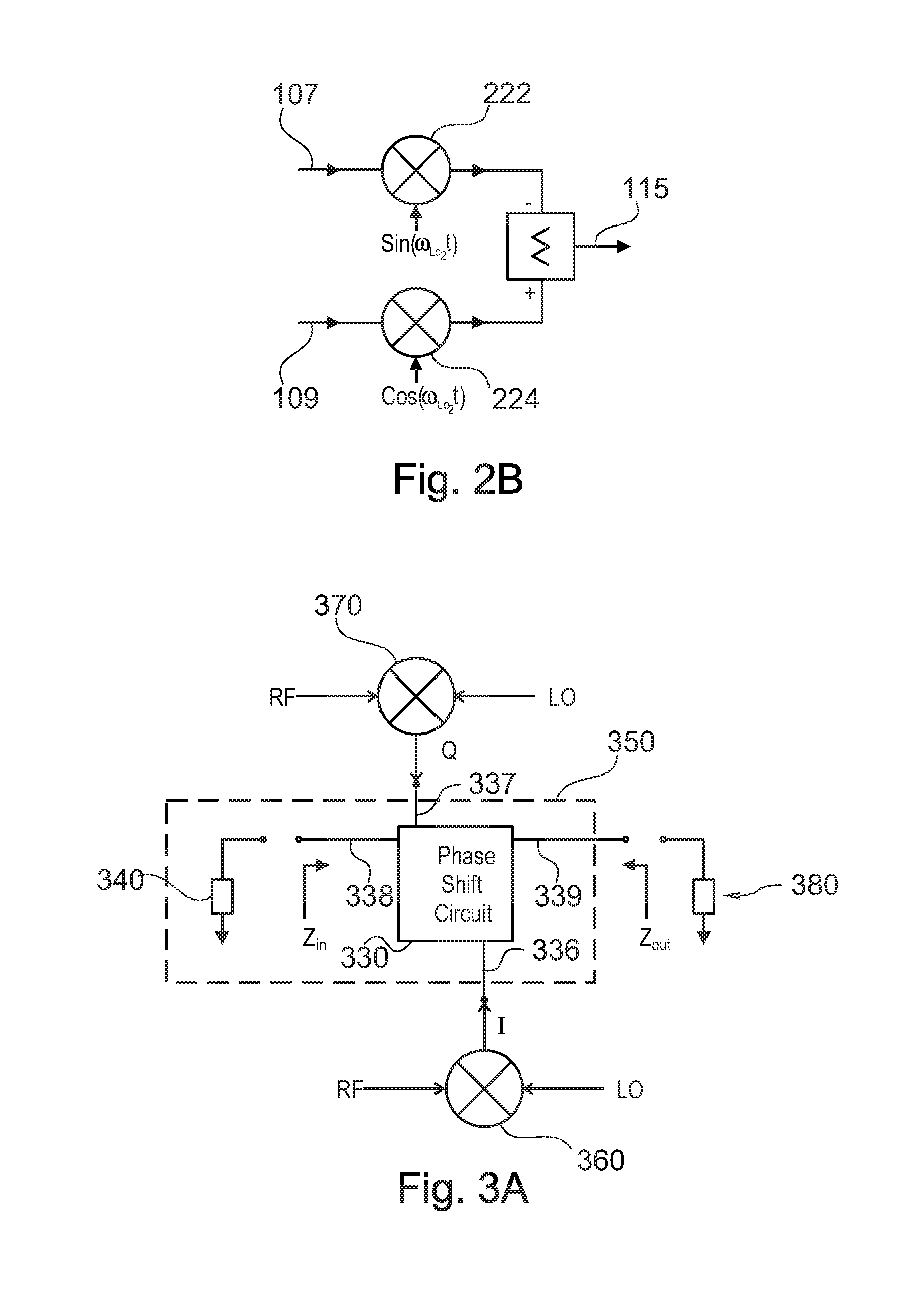
[0021]FIG. 3A illustrates a circuit block diagram of an image rejection circuit in accordance with one embodiment of the present invention. The image rejection circuit 300 includes an impedance-matched IQ network 350, in-phase and quadrature phase current mode mixers 360 and 370, and an output load 380 representing the equivalent impedance of the subsequent IF circuitry.

[0022]In the preferred embodiment, the impedance-matched IQ network 350 includes a phase shift circuit 330 and a back termination 340. The IQ network 350 operates to (...


PUM


Abstract

An impedance-matched IQ network includes a phase shift circuit and a back termination. The phase shift circuit includes an in-phase mixer port for receiving the in-phase signal, a quadrature-phase mixer port for receiving the quadrature phase signal, a termination port, and an output port. The back termination is coupled to the termination port of the phase shift circuit, the back termination having an impedance value substantially equal to the characteristic impedance of the phase shift circuit at the termination port.

Description

CROSS REFERENCE TO RELATED APPLICATIONS[0001]This application claims the benefit of U.S. Provisional Application No. 60 / 319,612, filed Oct. 11, 2002, the contents of which is herein incorporated by reference in its entirety for all purposes.BACKGROUND OF THE INVENTION[0002]Image rejection circuits are well known in the art of radio frequency communication systems. These circuits are commonly used to minimize or eliminate the unwanted RF image of the received signal, the reception and processing of which can add noise and distortion to the communication system.[0003]FIG. 1 illustrates a typical image rejection system employed in a communications receiver often referred to as the Harvey architecture. An RF signal 101 is provided to quadrature and in-phase mixers 104 and 106, respectively. An oscillator (not shown) supplies the in-phase mixer with an LO frequency cos(ωLOt) and the quadrature phase mixer 106 with the same LO frequency shifted 90 degrees sin(ωLOt). The quadrature and in-...

Claims


Application Information

Patent Timeline
Patent Type & Authority Patents(United States)
IPC IPC(8): H04B1/10H03D7/18H03H7/21H03H7/38
CPCH03D7/18H03H7/21H03H7/38
Inventor BARGROFF, KEITH P.
Owner ENTROPIC COMM INC
Features
  • R&D
  • Intellectual Property
  • Life Sciences
  • Materials
  • Tech Scout
  • Unparalleled Data Quality
  • Higher Quality Content
  • 60% Fewer Hallucinations
Learn More