Post passivation interconnection schemes on top of the IC chips

a technology of interconnection schemes and ic chips, applied in the field of postpassivation processing, can solve the problems of significant ir drop and power/ground noise, waste of expensive metal, and contaminated metal removal, and achieve the effect of high interconnection line resistan

Inactive Publication Date: 2008-05-13
QUALCOMM INC
View PDF60 Cites 58 Cited by
  • Summary
  • Abstract
  • Description
  • Claims
  • Application Information

AI Technical Summary

Benefits of technology

[0032]A principal objective of the invention is to provide a method for the creation of post-passivation interconnect metal that allows for the use of thick and wide metal.
[0036]Yet another objective of the invention is to provide a method that allows for the creation of long post-passivation interconnect lines, whereby these long post-passivation interconnect lines do not have high resistance or introduce high capacitance.

Problems solved by technology

There is significant IR drop and power / ground noise due to the high resistance and high capacitance of fine-line interconnect network.
This is a waste of expensive metal, especially for the cases when precious metal is used.
The removed metal is often contaminated and may not be able to be reused or may be very expensive to be reused.
It is difficult to achieve 100 times smaller RC product (per unit length) for the top layer metal of a fine line metallization system when compared to the bottom layer metal in the fine line metal interconnection process.
Essentially, it is hard for fine line IC metals to achieve even 10 times smaller RC product (per unit length) for its top metal layer versus its bottom metal layer.
This is because an inorganic material cannot be deposited as a thick layer of dielectric because such a layer of dielectric could develop fissures and crack as a result.
This is a waste of expensive metal, especially in those cases where precious metal such as gold, silver, or palladium is used.
The removed metal is often contaminated and may not be able to be reused or may be very expensive to reuse.The fine line interconnect lines must be fabricated in a stringent clean room environment of class 10 or less while the post-passivation interconnect lines can be fabricated in a much less expensive clean room environment of class 100 or more.The RC product (per unit length) —resistance times capacitance of the post-passivation interconnection lines is much smaller than the RC product of the fine line interconnect lines.

Method used


Image

  • Post passivation interconnection schemes on top of the IC chips
  • Post passivation interconnection schemes on top of the IC chips
  • Post passivation interconnection schemes on top of the IC chips

Examples


Embodiment Construction

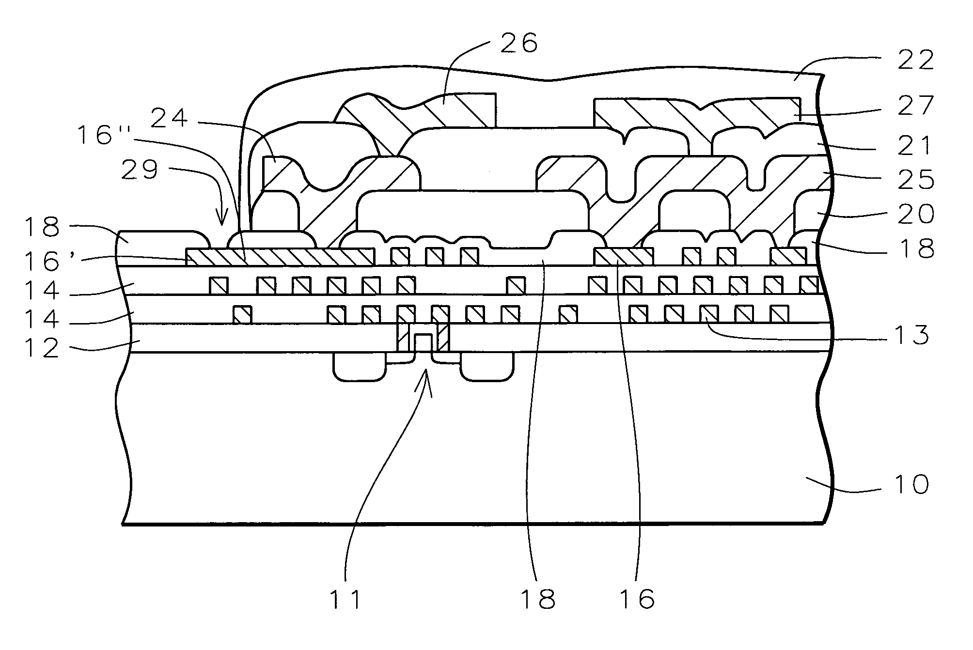
[0059]U.S. Pat. No. 6,383,916, to a common inventor as the current invention, teaches an Integrated Circuit structure where re-distribution and interconnect metal layers are created in layers of dielectric over the passivation layer of a conventional Integrated Circuit (IC). A layer of passivation is deposited over the IC, a thick layer of polymer is alternately deposited over the surface of the layer of passivation, and thick, wide metal lines are formed over the passivation.

[0060]Referring now more specifically to FIG. 6a, there is shown a cross section of one implementation of U.S. Pat. No. 6,383,916. The surface of silicon substrate 10 has been provided with transistors 11 and other devices (not shown in FIG. 6a). The surface of substrate 10 is covered by an interlevel dielectric (ILD) layer 12, formed over the devices.

[0061]Layers 14 (two examples are shown) represent all of the metal layers and dielectric layers that are typically created on the dielectric layer 12. Layers 14 ...


PUM


Abstract

A new method is provided for the creation of interconnect lines. Fine line interconnects are provided in a first layer of dielectric overlying semiconductor circuits that have been created in or on the surface of a substrate. A layer of passivation is deposited over the layer of dielectric and a thick second layer of dielectric is created over the surface of the layer of passivation. Thick and wide post-passivation interconnect lines are created in the thick second layer of dielectric. The first layer of dielectric may also be eliminated, creating the wide thick passivation interconnect network on the surface of the layer of passivation that has been deposited over the surface of a substrate.

Description

[0001]This application is a continuation-in-part of application No. 10 / 962,963, filed on Oct. 12, 2004, now pending.RELATED PATENT APPLCIATIONS[0002]This application is related to, Ser. No. 10 / 685,872, filed on Oct. 15, 2003, now pending, and to Ser. No. 10 / 278,106, filed on Oct. 22, 2002, now U.S. Pat. No. 6,734,563, which is a divisional of Ser. No. 09 / 691,497, filed on Oct. 18, 2000, now U.S. Pat. No. 6,495,442, all assigned to a common assignee and all incorporated herein by reference in their entirety.[0003]The application is also related to application No. 09 / 721,722, filed on Nov. 27, 2000, now U.S. Pat. No. 6,303,423, assigned to a common assignee and incorporated herein by reference in its entirety.BACKGROUND OF THE INVENTION[0004](1) Field of the Invention[0005]The invention relates to the fabrication of integrated circuit devices, and more particularly, to a method of post-passivation processing for the creation of conductive interconnects.[0006](2) Description of the Rel...

Claims


Application Information

Patent Timeline
Patent Type & Authority Patents(United States)
IPC IPC(8): H01L23/48H01L21/768H01L23/528H01L23/532H01L23/60
CPCH01L23/5286H01L23/5329H01L23/60H01L2924/3011H01L2924/0002H01L2924/00
Inventor LIN, MOU-SHIUNGCHOU, CHIU-MINGCHOU, CHIEN-KANG
Owner QUALCOMM INC
Why Eureka
Try Eureka