Roller link toggle gripper and downhole tractor

a technology of roller link and toggle gripper, which is applied in the direction of borehole/well accessories, drilling pipes, drilling rods, etc., can solve the problems of premature failure of fiber termination, extent of diametrical expansion, and limited use of downhole tractors, so as to improve the life prevent the loading of the roller mechanism, and improve the operation of the gripper assembly

Active Publication Date: 2008-07-01
WWT NORTH AMERICA HLDG
View PDF125 Cites 57 Cited by
  • Summary
  • Abstract
  • Description
  • Claims
  • Application Information

AI Technical Summary

Benefits of technology

[0033]In certain embodiments, various previously known improvements on roller-to-ramp interfaces may be applied to the interface between the roller mechanism and the inner surface of the roller link in a gripper. In some embodiments, the roller links include spacer tabs that prevent the loading of the roller mechanism when the toes are relaxed (non-gripping position), thus improving the life of the roller mechanism. In some embodiments, the roller links include alignment tabs that assist in maintaining an alignment between the roller mechanism and the inner surface of the roller link, thus improving operation of the gripper assembly. In some embodiments, the inner surfaces of the roller links are configured as inclined ramps having a relatively steeper initial incline followed by a relatively shallower incline. The steeper incline allows the toes to be expanded more quickly to a position at or near a borehole surface. The shallower incline allows a desired radial gripping force to be generated and the deflection of the toe link to be more finely adjusted.

Problems solved by technology

Tractors for moving within downhole passages are often required to operate in harsh environments and limited space.
As a result of the harsh working environment, space constraints, and desired force generation requirements, downhole tractors are used only in very limited situations, such as within existing well bore casing.
This design was susceptible to premature failure of the fiber terminations, subsequent delamination and pressure boundary failure.
The current embodiment of this gripper works exceedingly well, however in one current embodiment, there are limits to the extent of diametrical expansion, thus limiting the well bore variations compatible with the “Gripper” anchoring.
However, these gripper designs are either too large to fit within the small dimensions of a borehole or have limited radial expansion capabilities.
Also, the size of these grippers often cause a large pressure drop in the flow-by fluid, i.e., the fluid returning from the drill bit up through the annulus between the tractor and the borehole.
The pressure drop makes it harder to force the returning fluid up to the surface.
Also, the pressure drop may cause drill cuttings to drop out of the main fluid path and clog up the annulus.
While inflatable bladders provide good conformance to the possibly irregular dimensions of a borehole, they do not provide very good torsional resistance.
In other words, bladders tend to permit a certain degree of undesirable twisting or rotation of the tractor body, which may confuse the tractor's position sensors.
Additionally, some bladder configurations have durability issues as the bladder material may wear and degrade with repeated usage cycles.
Also, some bladder configurations may substantially impede the flow-by of fluid and drill cuttings returning up through the annulus to the surface.
As a result, the design is less effective in certain environments.
Also, this design impedes to some extent the flow of fluid and drill cuttings upward through the annulus.
Moving the gripper between its actuated and retracted positions involves substantial sliding friction between these sliding surfaces.
A major disadvantage of these grippers is that the sliding friction can significantly impede their operation, especially if the normal forces between the sliding surfaces are large.
The sliding friction may limit the extent of radial displacement of the gripping elements as well as the amount of radial gripping force that is applied to the inner surface of a borehole.
Thus, it may be difficult to transmit larger loads to the passage, as may be required for certain operations, such as drilling.
Another disadvantage of these grippers is that drilling fluid, drill cuttings, and other particles can get caught between and damage the sliding surfaces as they slide against one another.
Also, such intermediate particles can add to the sliding friction and further impede actuation and retraction of the gripper.
One major disadvantage of the four-bar linkage gripper design is that it is difficult to generate significant radial expansion loads against the inner surface of the borehole until the second link 203 has been radially displaced a substantial degree.
Thus, when the gripper is in or is near the retracted position, the gripper may be incapable of transmitting significant radial load to the borehole wall.
Thus, in small diameter environments, the gripper may not be able to reliably anchor the tractor.
As a result, this four-bar linkage gripper may not be useful in small diameter boreholes or in small diameter sections of generally larger boreholes.

Method used


Image

  • Roller link toggle gripper and downhole tractor
  • Roller link toggle gripper and downhole tractor
  • Roller link toggle gripper and downhole tractor

Examples


Embodiment Construction

Coiled Tubing Tractor Systems

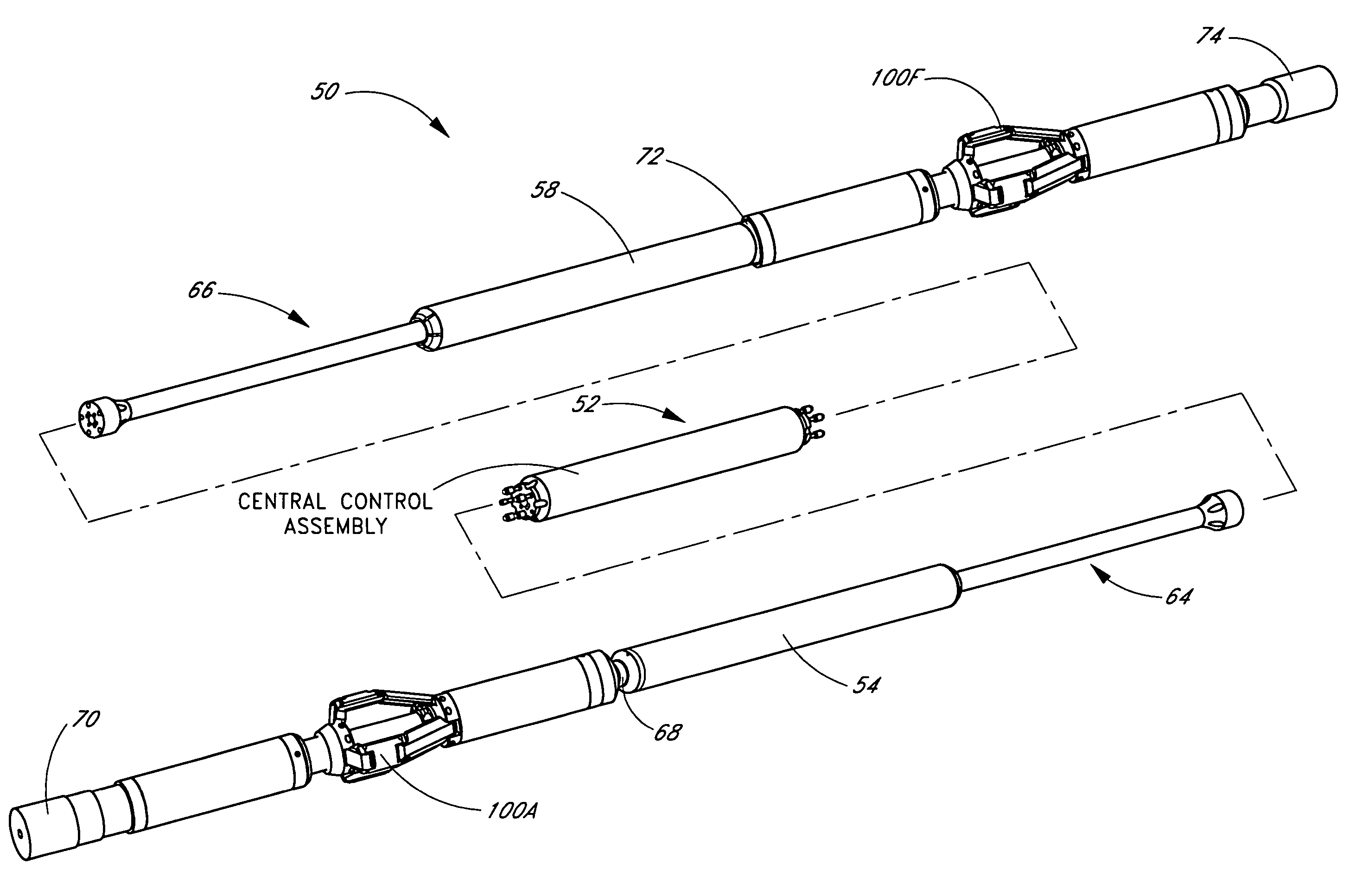
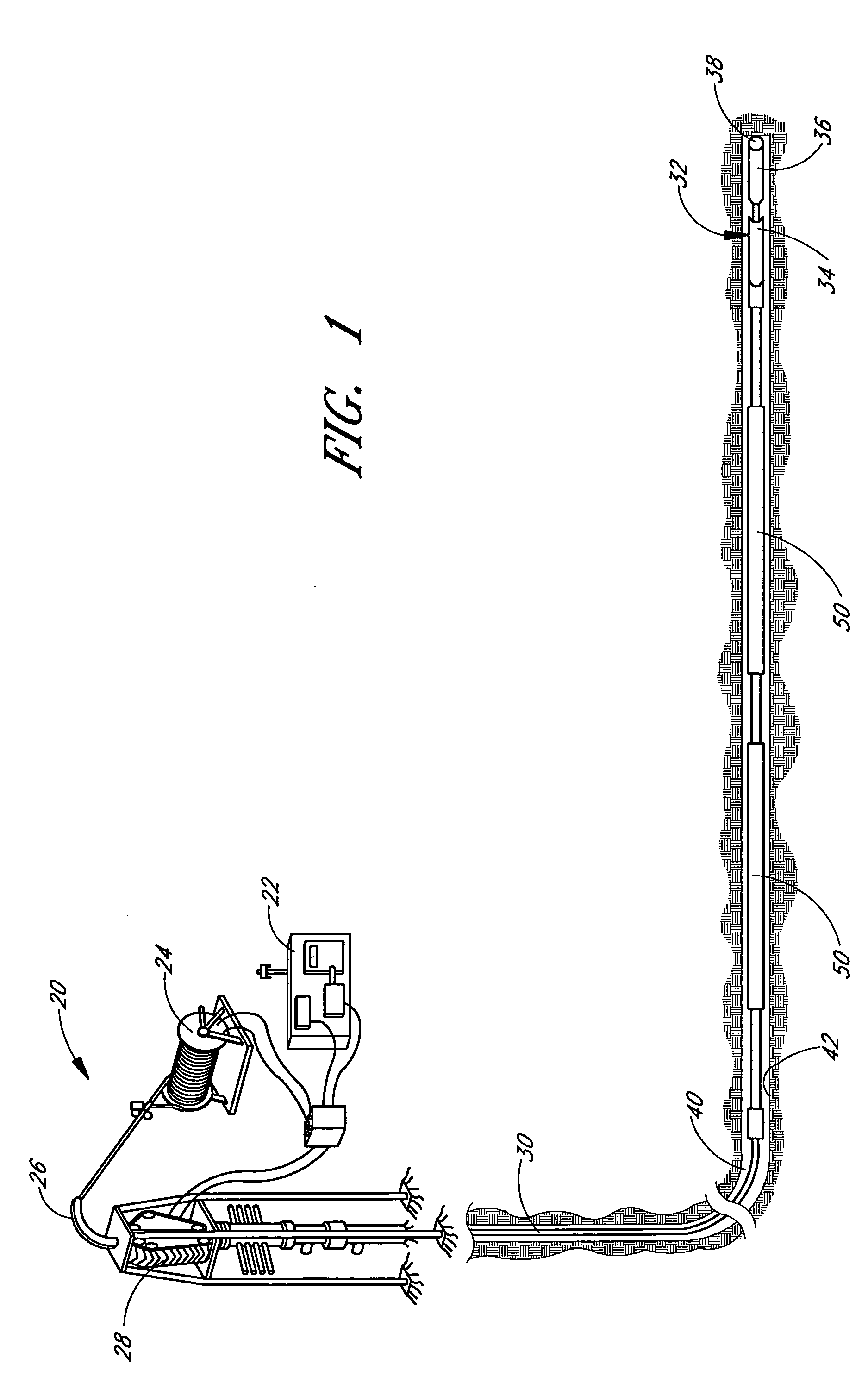
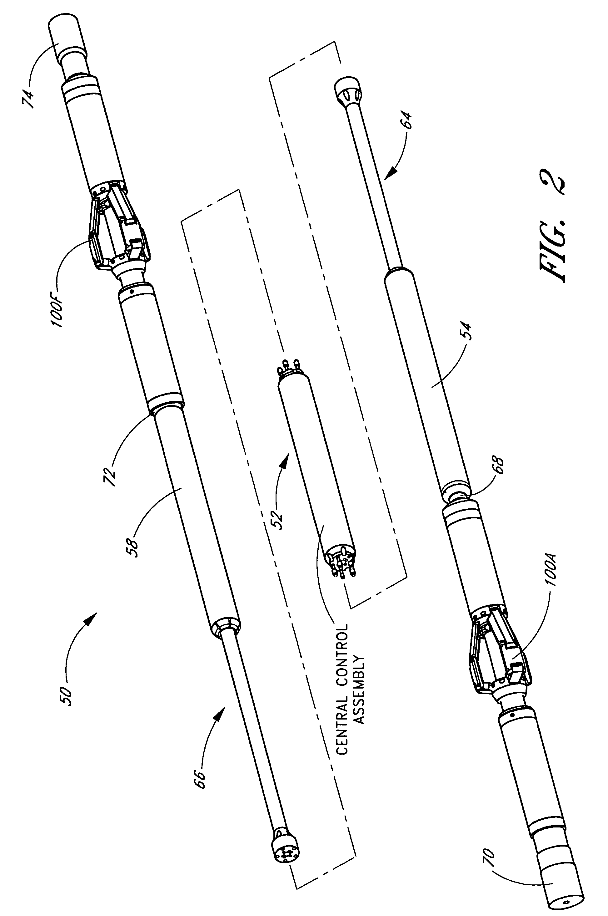
[0058]FIG. 1 shows a coiled tubing system 20 for use with two downhole tractors 50 connected by a drill string for moving within a passage. Connecting multiple tractors end-to-end may allow the use of smaller tractors, thereby facilitating maneuvering the coiled tubing system through a passage with relatively small radius turns. Although two downhole tractors 50 connected end-to-end are preferred in some applications, those of skill in the art will understand that a single tractor 50, or more than two tractors 50 could be used. Referring to FIG. 2, the illustrated tractor 50 has two gripper assemblies 100 according to the present invention. Although two gripper assemblies are preferred in some applications, those of skill in the art will understand that any number of gripper assemblies 100 may be used. In particular, one gripper assembly may be desirable, when a tractor is used in series with another tractor having two gripper assemblies. The coiled tubi...


PUM


Abstract

An expandable gripper assembly may be configured for anchoring a tool in a passage. The expandable gripper assembly includes first, second, and third pivotally connected links that are coupled to a tool. The third link is adapted to engage an inner wall in the passage. An actuation mechanism causes the third link to move radially outward from the tool for engagement with the inner wall. The actuation mechanism may comprise a roller mechanism that pushes on an inner surface of the first link for causing the first link to pivot outward away from the body. As the first and second links pivot outward, the third link moves in a radial direction for engagement with an inner wall.

Description

RELATED U.S. APPLICATION DATA[0001]This application claims the benefit of U.S. Provisional Patent Application No. 60 / 554,169, entitled “ROLLER LINK TOGGLE GRIPPER,” filed on Mar. 17, 2004; and U.S. Provisional Patent Application No. 60 / 612,189, entitled “ROLLER LINK TOGGLE GRIPPER,” filed on Sep. 22, 2004.[0002]Also, this application hereby incorporates by reference the above-identified provisional applications, in their entirety.BACKGROUND OF THE INVENTION[0003]1. Field of the Invention[0004]The present invention relates generally to gripping mechanisms for downhole tools.[0005]2. Description of the Related Art[0006]Tractors for moving within underground boreholes are used for a variety of purposes, such as oil drilling, mining, laying communication lines, and many other purposes. In the petroleum industry, for example, a typical oil well comprises a vertical borehole that is drilled by a rotary drill bit attached to the end of a drill string. The drill string may be constructed of...

Claims


Application Information

Patent Timeline
Patent Type & Authority Patents(United States)
IPC IPC(8): E21B4/18E21B23/00E21B23/04
CPCE21B4/18
Inventor MOCK, PHILIP W.MOORE, N. BRUCEBLOOM, DUANE
Owner WWT NORTH AMERICA HLDG
Why Eureka
Try Eureka