


Quick Research
Generate reliable direction feasibility study reports for your R&D in just a few steps.

Technical Q&A
Discover and master advanced knowledge NOW. Basics, ideas, possibilities, all at once.

Find Solutions
As an expert in R&D theories, this can generate solutions to your technical problems instantly.

Evaluate Feasibility
Analyze your overall solution with one click, know your potential R&D risks in advance.

Monitor Landscape
Get weekly tech updates, stay abreast of the latest tech innovations and key insights.
Seed generating circuit, random number generating circuit, semiconductor integrated circuit, IC card, and information terminal equipment
- Summary
- Abstract
- Description
- Claims
- Application Information
AI Technical Summary
Problems solved by technology
Method used
Image

Examples
first example
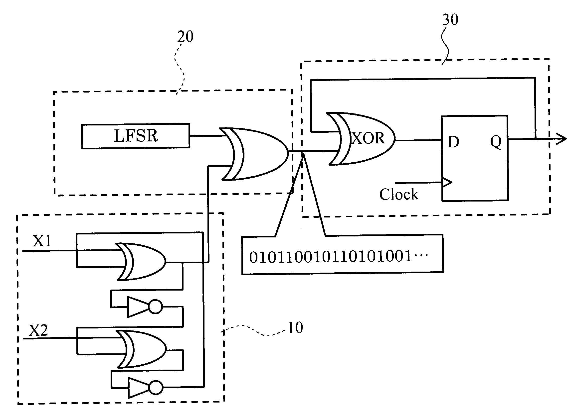
[0075]FIG. 6 is a block diagram showing the seed generating circuit according to the first example of the invention. That is, this seed generating circuit is provided the oscillating circuit 10 expressed in FIG. 2. As mentioned above, this oscillating circuit 10 is the “intermittent oscillating circuit”, which carries out the ring oscillation only when the two inputs X1 and X2 are different from each other. And if the case where the two inputs X1 and X2 are the same and the case where the two inputs X1 and X2 are different from each other are half and half, the oscillating circuit 10 oscillates only for the half time of the circuit operation.
[0076]On the other hand, the smoothing circuit 20 can be provided with LFSR which has the shift register with thirteen stages as pseudo random number output circuit 20A. The random number sequence illustrated is obtained by calculating XOR of the output of the oscillating circuit 10 and the output of LFSR in the smoothing circuit 20.
[0077]On the...
second example
[0086]FIG. 8 is a schematic diagram showing the seed generating circuit according to the second example of the invention. In this example, the ring oscillator which expressed in FIG. 3 is used as the oscillating circuit 10. That is, this example is the seed generating circuit in which the “continuous oscillating circuit” is used. In this case, it is desirable for the oscillation frequency of the oscillating circuit to be 10 or more times of the system clock in general. As mentioned above, it is desirable for the ring oscillating circuit of the oscillating circuit 10 to be asynchronous with other circuits.
[0087]On the other hand, the smoothing circuit 20 has the pseudo random number generating circuit 20A and the XOR operation media 20B. The pseudo random number generating circuit 20A calculates the logical sum (OR) of the logical product (AND) of the lowest two bits of LFSR which includes 11 stages of shift registers, and an inversion of the one bit of the next column. And then, the...
third example
[0090]Next, the example of transformation of the processing in the postprocessing circuit 30 will be explained as the third example of the invention.
[0091]FIG. 9 is a schematic diagram showing the seed generating circuit according to this example. The multiple of 4, i.e., 4n series data are generated in the smoothing circuit 20 in this example (n is an arbitrary number). The time series data are categorized in terms of every combination of four data in the postprocessing circuit 30 as shown in the figure, respectively, and are converted into “0” or “1.” A one bit is made by repeating this process n times.
[0092]Thus, the table (conversion table) to convert n bits into one bit is prepared, and by fabricating the conversion circuit for performing the conversion corresponding to this table by using logic circuits, the postprocessing circuit 30 can be realized. Here, the table must be made so that “0” and “1” may be converted out with equal probability. As long as such a condition is fil...
PUM
 Abstract
Description
Claims
Application Information
 - R&D Engineer
- R&D Manager
- IP Professional
- Industry Leading Data Capabilities
- Powerful AI technology
- Patent DNA Extraction
Browse by: Latest US Patents, China's latest patents, Technical Efficacy Thesaurus, Application Domain, Technology Topic, Popular Technical Reports.
© 2024 PatSnap. All rights reserved.Legal|Privacy policy|Modern Slavery Act Transparency Statement|Sitemap|About US| Contact US: help@patsnap.com