Internal combustion engine and a method for such an engine

a technology of internal combustion engine and combustion chamber, which is applied in the direction of machines/engines, electric control, speed sensing governors, etc., can solve the problems of increased material failure in the exhaust manifold, increased so as to reduce the thermal stress of the exhaust manifold. , the effect of effective reduction of the flow of cold air to the exhaust man

Active Publication Date: 2008-07-08
VOLVO CAR CORP
View PDF10 Cites 4 Cited by
  • Summary
  • Abstract
  • Description
  • Claims
  • Application Information

AI Technical Summary

Benefits of technology

[0003]Therefore, inventors herein have recognized it is important to make the manufacturing of exhaust manifolds for internal combustion engines less complex and cheaper and to reduce thermal stresses of an exhaust manifold for an internal combustion engine.
[0006]By controlling the throttle valve, if the flow of fuel injected into the cylinder is equal to or less than a fuel injection threshold value, so as to assume a not fully open position, the flow of relatively cold air through the engine, and through the exhaust manifold, will decrease. This will decrease the thermal stresses of an exhaust manifold of the engine when heated. In turn, this will reduce the need to make the manifolds in expensive high-temperature enduring materials.
[0007]The not fully open position of the throttle valve can be a position in which the throttle valve is less than fifty percent open, preferably less than twenty percent open. If during a motor brake condition of the engine the throttle valve is less than fifty percent open, the flow of cold air to the exhaust manifold is effectively reduced. The throttle valve being less than twenty percent open further reduces the flow of cold air to the exhaust manifold, while maintaining a sufficiently high pressure in the inlet manifold of most typical vehicle engines.
[0009]Preferably, the step of controlling the throttle valve is at least partly based on the engine speed. This provides a possibility to obtain at each given engine speed a good trade-off between the desire to reduce the flow of cold air to the exhaust manifold, and to maintain a sufficiently high pressure in the inlet manifold.
[0014]Preferably, the temperature of an exhaust manifold of the engine is determined, and the step of controlling the throttle valve is based on the exhaust manifold temperature. In a preferred embodiment, it is determined whether the temperature of the exhaust manifold is above a predetermined manifold temperature value, and the step of controlling the throttle valve is dependent on the exhaust manifold temperature being above the predetermined manifold temperature value. Thereby, unnecessary throttling, for example, immediately after a cold start of the engine when the exhaust manifold is not yet hot, can be avoided.

Problems solved by technology

The temperature difference can cause large thermal stresses in the exhaust manifold, in turn resulting in a risk of cracks appearing in the manifold.
A known way to solve this problem is to use high strength materials for the manifold, which, apart from being expensive, often have the disadvantage of being difficult to process when manufacturing the manifold.
The inventors have discovered that diesel engines subjected to a lot of overrun (motor brake), i.e., fuel injection shut-down while the crankshaft is turning, compared to engines subjected to less overrun, present higher amount of material failures in the exhaust manifold.

Method used


Image

  • Internal combustion engine and a method for such an engine
  • Internal combustion engine and a method for such an engine
  • Internal combustion engine and a method for such an engine

Examples


Embodiment Construction

)

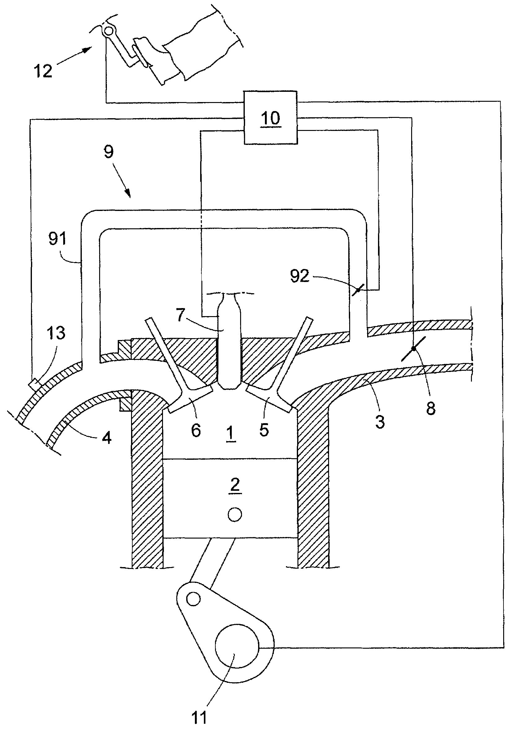
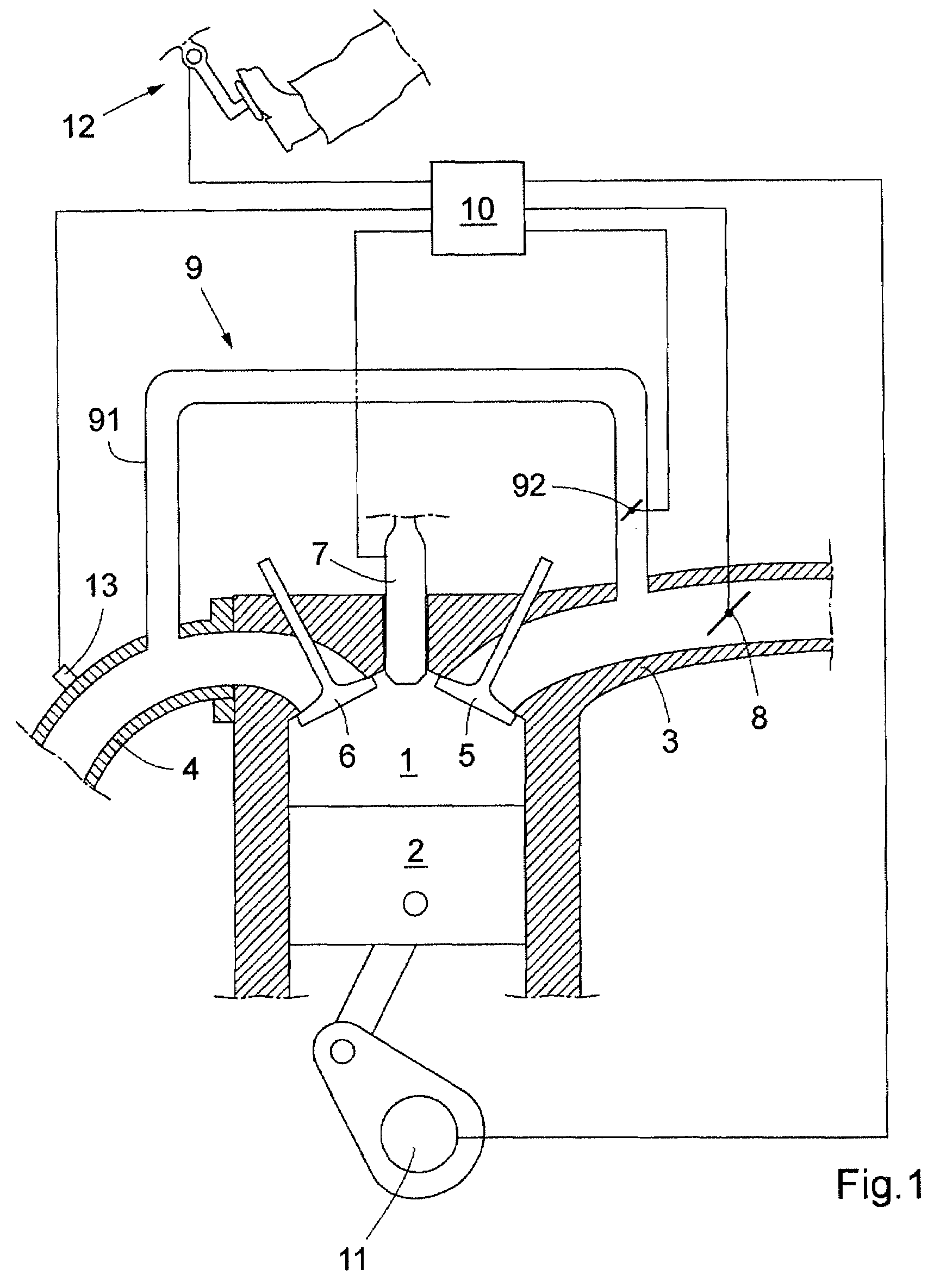
[0019]FIG. 1 shows schematically parts of an internal combustion engine, with compression ignition, for a vehicle. The engine comprises a cylinder 1 with a piston 2. The invention is suitable for engines with any number of cylinders. The engine further comprises an inlet and an exhaust manifold 3, 4, and an inlet and an exhaust valve 5, 6. A fuel injector 7 is arranged to inject fuel into the cylinder 2. More specifically, the fuel injector 7 is adapted to inject fuel periodically, at least once every work cycle of engine. A throttle valve 8 is provided in the inlet manifold 3 for controlling the air flow to the cylinders 2.

[0020]Further, in a manner known in the art, an exhaust gas recirculation (EGR) arrangement 9 is provided with a conduit 91 for guiding exhaust gas from the exhaust manifold 4 to the inlet manifold 3, and an exhaust gas recirculation (EGR) valve 92, for controlling the flow of re-circulated exhaust gas. The EGR arrangement 9, in particular the EGR valve 92, can ...


PUM


Abstract

A method for controlling a diesel engine in a vehicle is presented. The engine comprises at least one cylinder, a fuel injector for each cylinder for injecting fuel into the respective cylinder, and a throttle valve for controlling the flow of air into the cylinder. The throttle valve is adjusted to assume a not fully open position if an amount of fuel injected into the at least one cylinder is equal to or less than a fuel injection threshold value.

Description

TECHNICAL FIELD[0001]The present invention relates to an internal combustion engine for a vehicle, and more particularly to a diesel engine comprising at least one cylinder, a fuel injector for each cylinder for injecting fuel into the respective cylinder, and a throttle valve for controlling the flow of air into the cylinder.BACKGROUND AND SUMMARY OF THE INVENTION[0002]In a normal operational situation of a vehicle engine, the difference between the exhaust gas temperature, and the ambient air temperature can reach 800° C. or more. The temperature difference can cause large thermal stresses in the exhaust manifold, in turn resulting in a risk of cracks appearing in the manifold. A known way to solve this problem is to use high strength materials for the manifold, which, apart from being expensive, often have the disadvantage of being difficult to process when manufacturing the manifold.[0003]Therefore, inventors herein have recognized it is important to make the manufacturing of ex...

Claims


Application Information

Patent Timeline
Patent Type & Authority Patents(United States)
IPC IPC(8): F02D31/00F02D33/00
CPCF02D41/0005F02D41/123F02D41/0047Y10T477/747F02D2041/0022Y02T10/42F02D41/1446Y02T10/40
Inventor MOLLER, KJELLGUSTAVSSON, DANIELANDREASSON, MARTIN
Owner VOLVO CAR CORP
Why Eureka
Try Eureka