Internal UV treatment of potable water systems

a technology of uv treatment and potable water, applied in the direction of separation process, filtration separation, instruments, etc., can solve the problems of inability to reduce biofilm on the interior of the tank, the nature of the water supply is massive and wholly unsuitable for portable or vehicular use, and the treatment is at most only partially effective, so as to reduce or eliminate the accumulation of microorganisms and biofilm

Inactive Publication Date: 2008-07-08
THORPE GEORGE W
View PDF34 Cites 28 Cited by
  • Summary
  • Abstract
  • Description
  • Claims
  • Application Information

AI Technical Summary

Benefits of technology

[0036]The above-noted problems, and others, are overcome in accordance with the present invention, by an improved method and apparatus which utilizes one or more germicidal UV lamps inside any one, or several of the individual water-holding components of the potable water supply. Preferably the UV germicidal lamps are installed in two or more of the following devices: water tank, water heater, water faucet, water accumulator, etc. With this arrangement it has been discovered that the conventional POE UVDU can be eliminated from the system.
[0037]Experimentation in the present invention has shown that UV lamp or lamps, installed inside dispersed water holding / supply devices, provides much broader disinfection and reliability to the potable water supply than when a POE UVDU is utilized. The reliability increase from having two independent, redundant sources of UV disinfection rather than one, is much more than double. Dispersing the UV lamps also reduces the buildup of biofilms throughout the water supply. This enhanced UV disinfection allows a very low residual level of chlorine, previously added to the municipal water supply, to control bacteria that is in suspension in the water.
[0038]The water holding / supply devices act as the container for the UV lamps, eliminating the need for the POE UVDU. The increased system weight of the extra UV lamps and ballasts are more than offset by the weight reduction achieved by eliminating the UVDU.

Problems solved by technology

However, as noted above, in the bulk of these devices the water is exposed to the UV radiation only as it flows through one portion or point in the system.
As a result, the treatments are at most only partially effective and the devices share many of the deficiencies discussed above as well as other drawbacks.
UV treatment only occurs in the mixing section, and in any event the system is by its nature massive and wholly unsuited to portable or vehicular use.
None of these references are concerned with or effective at reducing biofilm on the interior of the tank, piping, or the other water supply components.
This POE UVDU also has many of the limitations described above.
While effective for disinfection of water that passes through the unit, it will not control the bacteria, viruses and biofilm that grow in the other devices and piping that are part of the potable water supply.
Walker employs POE water treatment devices, comprising a filter and / or an ultra-violet disinfection device, as the only means of disinfection and therefore shares many of the above deficiencies, e.g, the apparatus will not control the bacteria, viruses and biofilm that grow in the other devices that are part of the potable water supply system.
This approach does not recognize the dangerous buildup of bacteria and biofilm in the airflow duct where water or mist is introduced.
However, no disinfection of the sponge or tank is accomplished, thereby allowing growth of bacteria and biofilm.

Method used


Image

  • Internal UV treatment of potable water systems
  • Internal UV treatment of potable water systems
  • Internal UV treatment of potable water systems

Examples


Embodiment Construction

[0064]The following description of the preferred embodiments is not meant to be a limitation of other possible modes for implementing the principles of the present invention.

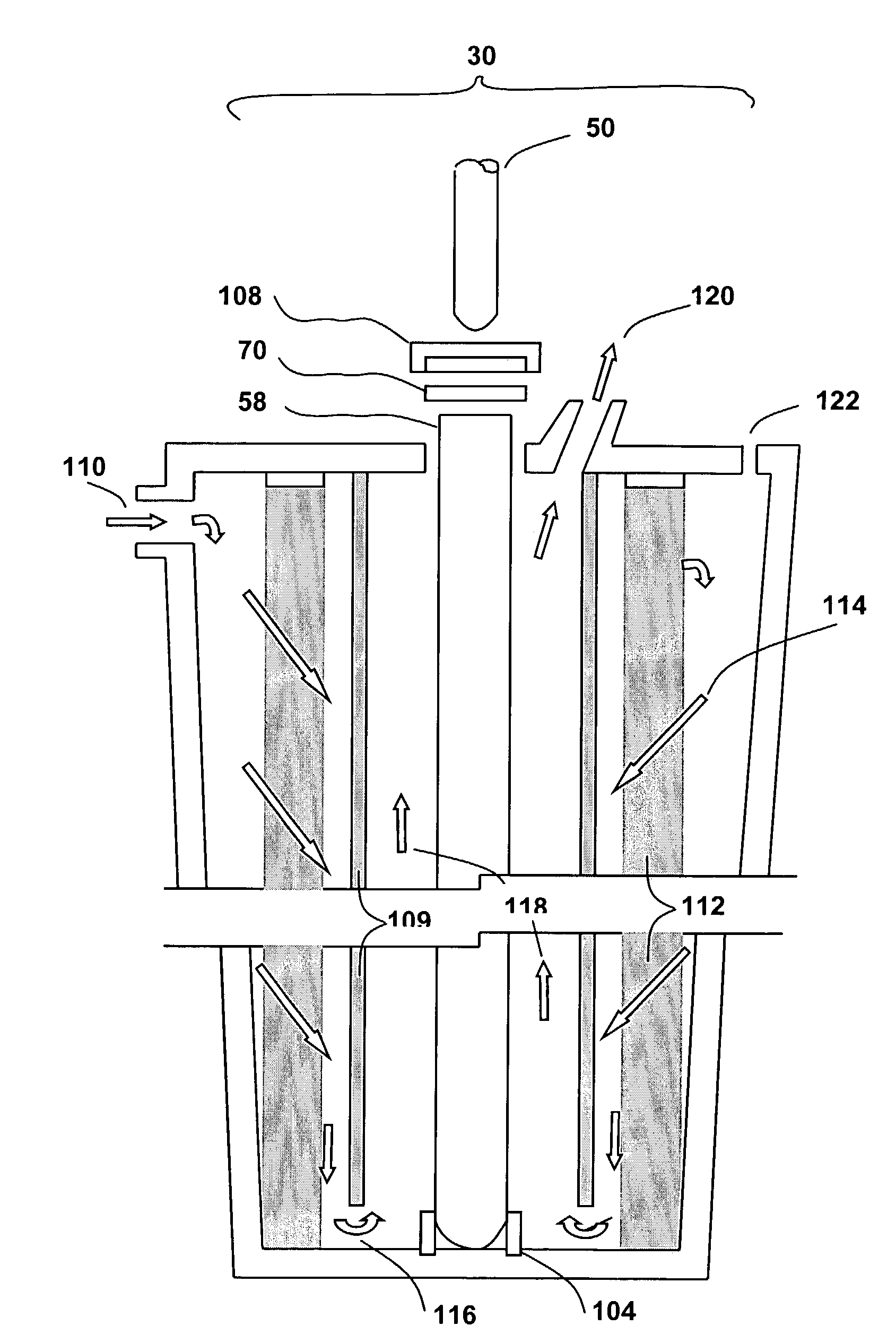
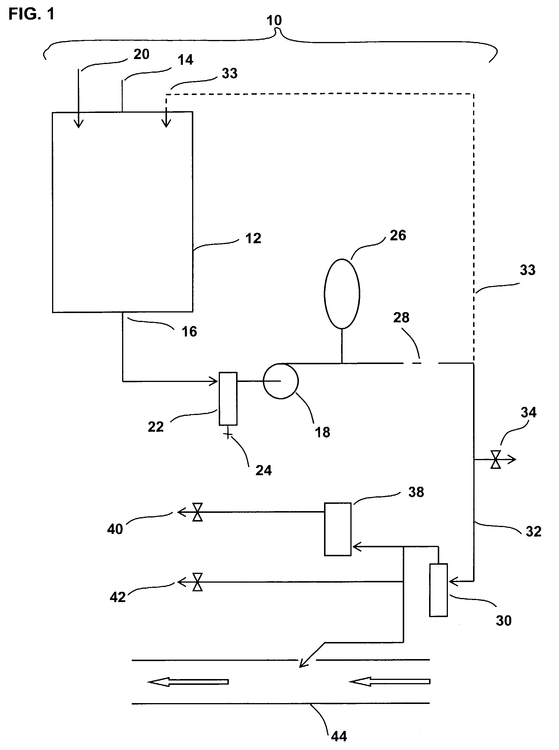
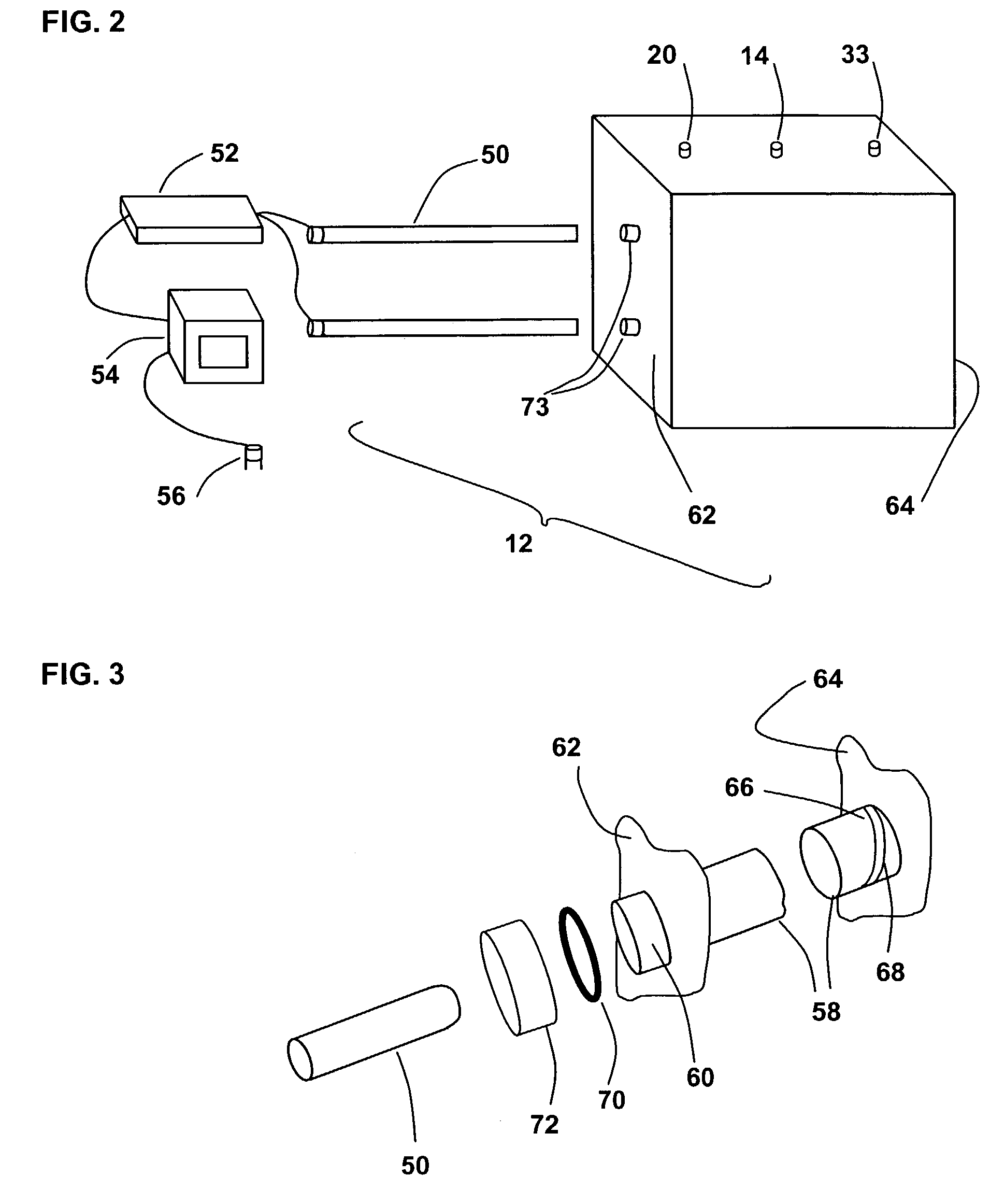
[0065]The present invention provides a system for effective UV treatment of potable water, for a mobile or small self-contained potable water system in which the water is stored or resident in one or more tanks or vessels. By “resident” it is meant that the water rests or remains to some extent within the vessel or other components during operation of the system, as opposed to simply flowing through it. In contrast to the prior art, the present invention thus employs UV light sources that are positioned within the tanks and other vessels, rather than relying solely on a “flow past” approach. The UV lamps are mounted in quartz tubes within the vessels, and are preferably supported against damage by vibration. A similar structure is provided for mounting a UV lamp within the interior of an outlet faucet. In additi...


PUM

PropertyMeasurementUnit
pressure dropaaaaaaaaaa
volumeaaaaaaaaaa
photocatalyticaaaaaaaaaa

Abstract

A UV disinfectant system for treatment of water resident in a vessel. One or more UV lamps are mounted within the interior of the vessel so as to expose the water stored therein. The vessel may be, for example, a water tank, water heater, water filter or other component which holds a volume of water. A layer of photoreactive material may be formed on an inside surface of a wall of the vessel so as to be exposed to the UV radiation from the lamp. The photoreactive material may be tin dioxide, titanium dioxide, or other material that produces hydroxyl ions in response to UV exposure. The hydroxyl ions flow from the vessel into the piping and other components of the system so as to inhibit microbial action therein. The UV lamps may be mounted in quartz sleeves that surround the lamps for immersion in water and that are supported to protect the sleeves and lamps from vibration damage. The system may also be used to prevent freeze damage to the vessel and water system.

Description

BACKGROUND[0001]a. Field of the Invention[0002]This invention relates to an improved method and apparatus for the inactivation of microorganisms and reduction of biofilm in a self-contained potable water supply, or on the interior surfaces of devices used in the system. This is accomplished in part by installing one or more (UV) germicidal lamps inside at least one and preferably two or more of the following components: potable water tank, faucet, filter, water heater, humidifier. Additional microorganism inactivation and biofilm reduction can be provided through the use of a titanium dioxide, tin dioxide or other UV-activated antibacterial liner on the walls and welds of the components. The potable water supply may be installed in a remote portable structure or in a mobile vehicle such as a train, boat, bus, motor home, aircraft, and the like.[0003]b. Background[0004]Contamination of vehicular and other self-contained water systems is a significant ongoing problem. The World Health...

Claims


Application Information

Patent Timeline
Patent Type & Authority Patents(United States)
IPC IPC(8): C02F1/32C02F1/30C02F1/72
CPCC02F1/325C02F1/725C02F2201/008C02F2307/06C02F2201/3227C02F2209/42C02F2305/10C02F2201/009Y02A20/211Y02A20/212Y02A20/208
Inventor THORPE, GEORGE W
Owner THORPE GEORGE W
Why Eureka
Try Eureka