Radiation imaging apparatus and control method therefor

a technology of radiography apparatus and control method, which is applied in the direction of radiography controlled devices, instruments, applications, etc., can solve the problems of preventing the delay between pressing the irradiation switch and ejecting x-rays, not providing a stable photoelectric conversion proportional to the x-ray dose, and unable to synchronize the reading operation of the x-ray imaging apparatus with the x-ray emission, so as to achieve stable radiography and prevent the delay radiation

Inactive Publication Date: 2008-07-22
CANON KK
View PDF28 Cites 53 Cited by
  • Summary
  • Abstract
  • Description
  • Claims
  • Application Information

AI Technical Summary

Benefits of technology

[0022]The present invention provides a radiation imaging apparatus capable of stably performing radiography while preventing a delay of radiation emission, and a control method for the radiation imaging apparatus.
[0025]In another aspect of the present invention, a radiation imaging system includes a radiation generator, a conversion circuit unit in which a plurality of pixels including conversion elements are arranged into an array on a substrate, a reading circuit unit that reads signals from the conversion circuit unit, and a radiation emission switch for instructing the radiation generator to emit radiation. A radiation image is taken in a radiographic operation period that includes an idling operation period prior to emission of radiation and a reading operation period subsequent to emission of radiation. A radiation-induced signal is indicated to a radiographer during the idling operation period so that the radiographer can operate the radiation emission switch at a desired time subsequent to the idling operation period, and the radiation generator emits radiation when the radiation emission switch is operated.
[0031]According to the present invention, stable photoelectric converted signals having small dark current variations in proportional to the dose of applied radiation can be obtained. The irradiation switch is operated in synchronization with a radiation-induced signal, thus allowing radiography with small radiation delay at desired timing. Moreover, a radiographer can operate the irradiation switch while perceiving the radiation-induced signal, and therefore no electrical connection via a cable between the radiation imaging apparatus and the radiation generator is required. Thus, a portable radiation imaging apparatus, such as a film cassette type apparatus, can be realized, which is easy-to-use and safe even in emergency medical environments in which a patient is radiographed while moving the radiation generator.

Problems solved by technology

In an X-ray imaging apparatus of the related art, generally, photoelectric conversion elements made of amorphous semiconductor as a main material, such as amorphous silicon or amorphous selenium, do not provide a stable photoelectric conversion in proportion to the X-ray dose due to dark current variations immediately after applying a bias.
However, the idling operation period makes it difficult to synchronize a reading operation of the X-ray imaging apparatus with X-ray emission.
However, this control method causes a delay between pressing the irradiation switch and emitting X-rays.
However, medical X-ray imaging apparatuses for use in simple thoracic radiography generally have a wide radiographic range and a large number of pixels, and therefore require approximately 0.1 to 1 seconds for reading.
X-ray radiography using such medical X-ray imaging apparatuses can make radiographers uncomfortable.
Another problem is that a desired image cannot be obtained due to a delay although a radiographer presses the irradiation switch at a desired time.
Therefore, the chance of taking the best radiographs may be lost.
The connection cable is inconvenient for the radiographer particularly in radiography using a portable X-ray imaging apparatus, such as a film cassette type apparatus, and reduces the radiographic efficiency.
An X-ray imaging apparatus having a connection cable can break down due to the cable being tripped over or walked on, and the radiographic operation is interrupted until the broken apparatus is repaired.

Method used


Image

  • Radiation imaging apparatus and control method therefor
  • Radiation imaging apparatus and control method therefor
  • Radiation imaging apparatus and control method therefor

Examples


first embodiment

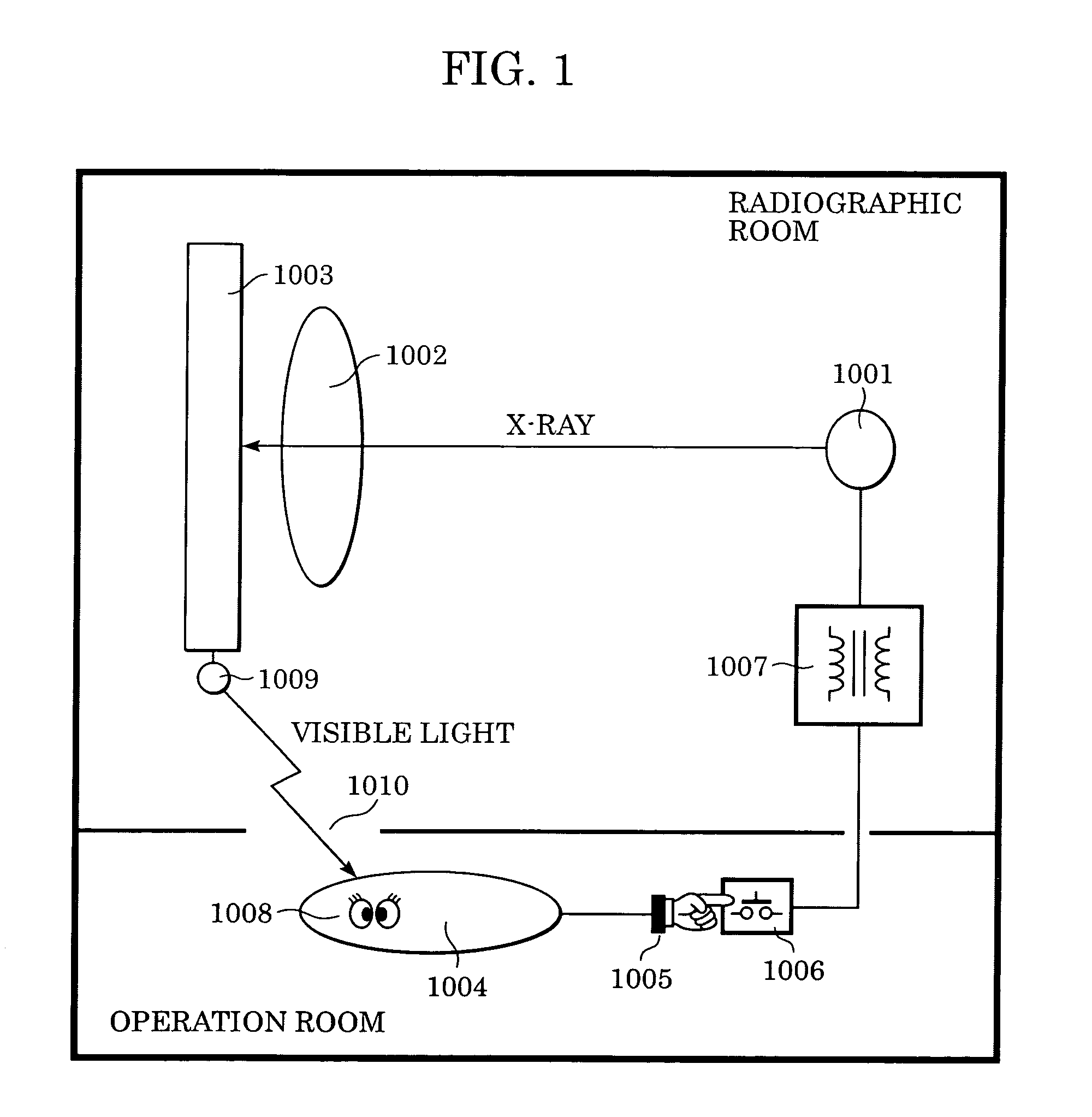
[0044]FIG. 1 is a diagram of an X-ray imaging system (radiation imaging system) according to a first embodiment of the present invention.

[0045]An X-ray source 1001 generates X-rays by allowing thermo-electrons emitted from a cathode filament disposed in a vacuum tube (not shown) to accelerate and strike an anode target. The target is made of, for example, tungsten or copper. A high-voltage power supply 1007 is a power supply for accelerating the thermo-electrons. When an irradiation switch 1006 is turned on, X-rays are produced from the X-ray source 1001. The irradiation switch 1006 is operated by, for example, a radiographer's hand 1005. An electron accelerating voltage (tube voltage) and a cathode filament current (or tube current) (not shown) are set in advance by a radiographer 1004 operating an operation panel (not shown).

[0046]In a radiographic room, the X-rays emitted from the X-ray source 1001 are applied to a patient 1002, and an X-ray imaging apparatus 1003 is exposed to t...

second embodiment

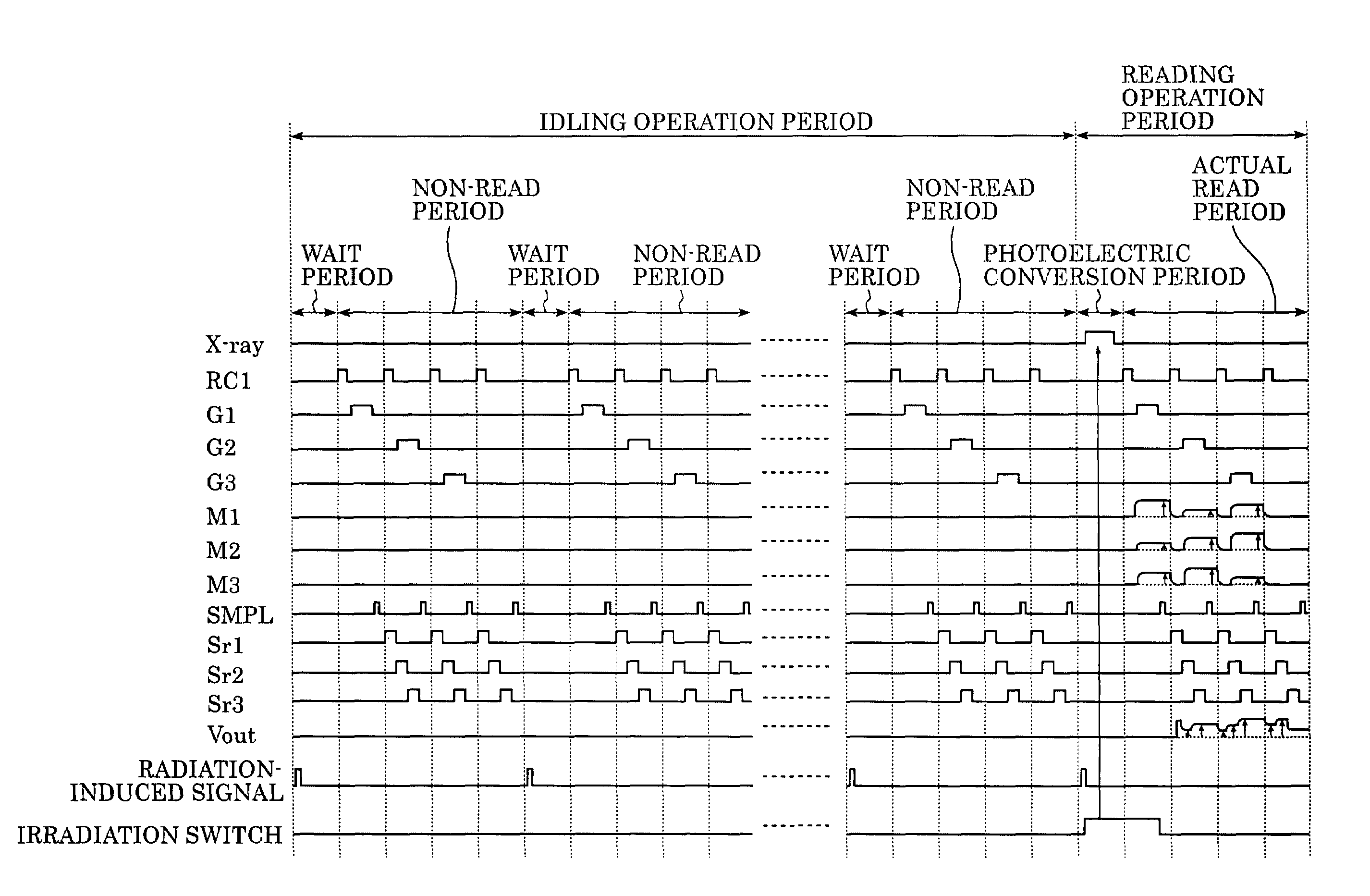
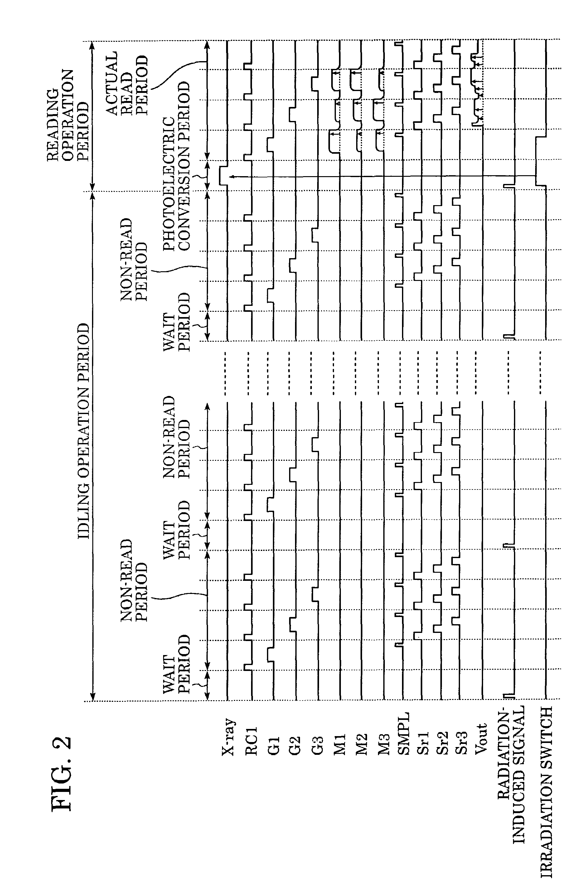
[0064]FIG. 3 illustrates an X-ray imaging system (radiation imaging system) according to a second embodiment of the present invention.

[0065]The X-ray imaging system according to the second embodiment includes a loudspeaker 1012, in place of the lamp 1009 in the X-ray imaging system according to the first embodiment, for generating an audio radiation-induced signal instead of an optical signal. The other structure of the X-ray imaging system is similar to that of the first embodiment. For a description of elements 1001, 1007, 1005, 1006, 1002, and 1010 of FIG. 3, see the description of the first embodiment.

[0066]The X-ray imaging system according to the second embodiment is also operated according to the timing chart shown in FIG. 2. Specifically, an audio radiation-induced signal is output from the loudspeaker 1012 during the idling operation period of the X-ray imaging apparatus 1003. The radiographer 1004 perceives the audio radiation-induced signal by his / her ear 1011, and turns ...

third embodiment

[0068]FIG. 4 illustrates an X-ray imaging system (radiation imaging system) according to a third embodiment of the present invention.

[0069]The X-ray imaging system according to the third embodiment includes an infrared LED 1013 for emitting infrared light, in place of the lamp 1009 in the X-ray imaging system according to the first embodiment. In the operation room, the X-ray imaging system according to the third embodiment further includes an infrared sensor 1014 for detecting infrared light emitted from the infrared LED 1013, and a loudspeaker 1012 connected to the infrared sensor 1014. For a description of elements 1001, 1007, and 1010 of FIG. 4, see the description of the first embodiment.

[0070]The X-ray imaging system according to the third embodiment is also operated according to the timing chart shown in FIG. 2. Specifically, a radiation-induced signal (infrared light) is emitted from the infrared LED 1013 during the idling operation period of the X-ray imaging apparatus 1003...


PUM


Abstract

A lamp emits pulse-shaped visible light when a wait period begins. If a radiation emission switch is not pressed in the wait period, X-ray radiation is not emitted from an X-ray source, and no charges are accumulated in photoelectric conversion elements of an X-ray imaging apparatus. In a non-read period, although signals are sequentially read from the photoelectric conversion elements, an output signal does not change. When the radiation emission switch is pressed in synchronization with a radiation-induced signal in a certain wait period, the X-ray source emits X-rays. After irradiation of X-rays, a photoelectric conversion period transitions to an actual read period. In the photoelectric conversion period, X-rays are emitted and transmitted X-ray information of a patient are accumulated in the photoelectric conversion elements of the X-ray imaging apparatus. In the actual read period, the accumulated information is read.

Description

BACKGROUND OF THE INVENTION[0001]1. Field of the Invention[0002]The present invention relates to a radiation imaging apparatus suitable for a variety of applications, such as medical diagnosis and industrial non-destructive inspection, and to a control method for the radiation imaging apparatus. In the present invention, radiation includes electromagnetic radiation, such as X-ray and γ-ray, α-ray, and β-ray.[0003]2. Description of the Related Art[0004]Generally, X-ray radiography systems used in hospitals are of a film radiography type and an image processing type. In a film radiography type system, a patient is irradiated with X-rays and a film is exposed to the X-rays transmitted through the patient. In an image processing type system, the X-rays transmitted through the patient are converted into electrical signals for digital image processing.[0005]One X-ray radiography system of the image processing type is a radiation imaging apparatus including a phosphor for transforming X-ra...

Claims


Application Information

Patent Timeline
Patent Type & Authority Patents(United States)
IPC IPC(8): H05G1/56G01T1/24H05G1/64A61B6/00
CPCA61B6/00A61B6/467A61B6/4233
Inventor ENDO, TADAOKAMESHIMA, TOSHIOYAGI, TOMOYUKITAKENAKA, KATSURO
Owner CANON KK
Why Eureka
Try Eureka