Method for the production of particles

a technology of particle and production method, applied in the field of particle production, can solve the problems of reducing the efficacy of a preparation containing the active ingredients, destroying the crystal form, and inevitable rise in the solid temperatur

Inactive Publication Date: 2008-07-29
GLAXO GROUP LTD
View PDF13 Cites 56 Cited by
  • Summary
  • Abstract
  • Description
  • Claims
  • Application Information

AI Technical Summary

Problems solved by technology

Unfortunately, all forms of mechanical grinding, milling, micronizing or attrition of solids to powders result in the destruction of the crystal form and in the introduction to the powder of heat energy with an inevitable rise in temperature of the solid.
However, it may in some cases cause a reduction in the efficacy of a preparation containing the active ingredients.
However, even this process can never be performed without destruction of the crystalline form of a material.
This process has disadvantages that prevent wide-scale use for the general preparation of small particles of some compounds, for example, pharmaceutically active ingredients.
The introduction of heat to the injected liquor could cause decomposition of a pharmaceutically active ingredient.
Exposure to air could result in the oxidation of a component.
Furthermore, all components desired to be produced by this

Method used


Image

  • Method for the production of particles

Examples


example 1

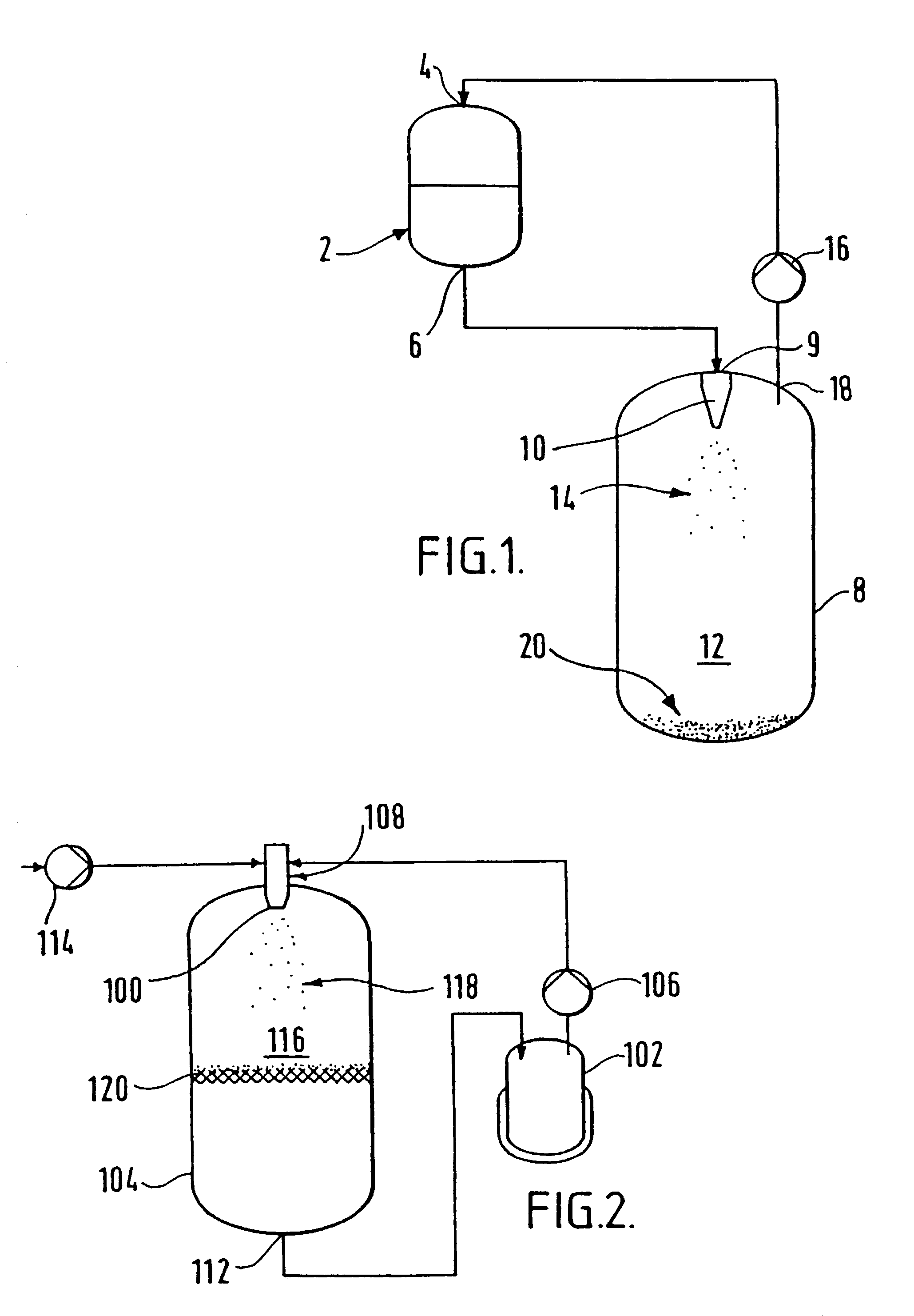
[0097]Phenyl acetic acid (10 g) was charged into a first vessel equipped with an agitator and a glass sinter attached to a bottom outlet.

[0098]Keeping the lower outlet of the first vessel closed, 1,1,1,2-tetrafluoroethane (2 kg) was charged into the first vessel. The slurry thus formed was agitated to achieve dissolution of the phenyl acetic acid in the tetrafluoroethane.

[0099]The inlet of a gas compressor was fitted to a second (evaporation) vessel and the outlet was fitted to a tetrafluoroethane storage vessel, via a cooling heat exchanger. The gas compressor was activated.

[0100]The mixture of phenyl acetic acid in tetrafluoroethane was allowed to flow from the first vessel to the second vessel via a flow restriction device, for example, a small aperture nozzle. The solution flow and temperature in each of the first and second vessels was controlled so that the pressure in the first vessel was maintained at about 6 BarG, and the pressure in the second vessel was maintained at abou...

example 2

[0102]A first 5 liter stainless steel vessel was connected to a liquid / liquid mixing flow cell via a gas compressor. A second 5 liter stainless steel vessel was fitted with a filter element fashioned from a sheet glass sinter at the outlet thereof. The inlet of the vessel was connected to the liquid / liquid mixing flow cell.

[0103]Hydrofluorocarbon 134A (HFC) (2 kg) was charged into the first vessel. The compressor was activated, so that the HFC was continuously recycled. The HFC recycling rate was maintained at 300 g / minute.

[0104]A solution of lauric acid (50 g) dissolved in acetone (1 liter) was prepared in a third vessel. The lauric acid solution was introduced into the mixing cell using a gear pump at a flow rate of 30 ml / minute.

[0105]The HFC contacted the lauric acid solution upon exiting the mixing cell. The mixture was sprayed into the second vessel by means of the mixing cell. Upon contacting the lauric acid solution, the acetone was transferred to the HFC by mass transfer. Up...


PUM

PropertyMeasurementUnit
Temperatureaaaaaaaaaa
Boiling pointaaaaaaaaaa
Polarityaaaaaaaaaa

Abstract

A method of preparing particles of a substance, for example selected from a flavor, fragrance, pigment, dye, biologically active compound or a plastics material, comprises contacting the substance of a formulation (which may include the substance in conjunction with a second solvent) with a first solvent which comprises a C1-C4 hydrofluorocarbon, especially tetrafluoroethane, and subjecting the resultant mixture to a separation process, for example, by allowing the mixture to be sprayed as a mist (14) from a high pressure environment in a first vessel (2) to a low pressure environment in a second vessel (8), thereby to cause separation of a least some of the substance from the first solvent and the formation of fine particles (20) of the substance.

Description

FIELD OF THE INVENTION[0001]The present invention relates to the production of particles and, in particular, but not exclusively, to the production of particles having a controlled size and / or defined crystalline form.BACKGROUND OF THE INVENTION[0002]Many industries require that their solid particulate raw materials meet rigorous specifications as to size and shape. Some require very small particles or crystals with closely defined limitations as to the range of size and shape.[0003]In the food industry, it would be advantageous to obtain raw materials as solid particulate powders having very small, narrowly distributed mesh sizes in order to distribute more evenly the flavour ingredient throughout their prepared food-stuff products.[0004]Industries concerned with colour in the form of dye-stuffs and pigments need small, uniform, closely defined particulate materials, to distribute better and more evenly such dyes and pigments in suspension or solution throughout their paints, print...

Claims


Application Information

Patent Timeline
IPC IPC(8): B01D9/00A23L27/00A61K9/14B01J2/02C07B63/00C09D17/00
CPCB01D9/0027B01J2/02B01D9/005
Inventor NICOLA, MAZIN
Owner GLAXO GROUP LTD
Why Eureka
Try Eureka