
Self-adjusting dual technology occupancy sensor system and method

Inactive Publication Date: 2008-08-12
EATON INTELLIGENT POWER LIMITED
View PDF32 Cites 156 Cited by
  • Summary
  • Abstract
  • Description
  • Claims
  • Application Information

AI Technical Summary

Benefits of technology

[0015]The system self-adjusts the sensitivity and time delay thereof in real time to enhance performance and reduce the need for follow-up adjustments. Coverage of the area remains stable regardless of environmental conditions therein. Concurrent time delays for the sensor sections avoids inadvertent deactivation in occupied areas.
[0016]Installation is simplified with a delay default when the system is left at minimum potentiometer setting. Environmental motion tolerant systems resist false activation in environmentally active areas such as high airflow rooms. DIP switch selectable lighting sweep setting reduces activations following power sweeps for example in facilities with computer control system. A zero time delay DIP switch is adapted for use in building automation systems and alarm modes for business management systems equipped with an internal timing function. An alarm function avoids false alarm activation, through detection redundancy testing.
[0017]A manual on / off option via a wall switch enables a building automation system relay to remain active during occupancy. The system is fully self-resetting, whereby upon manual deactivation in automatic activation mode, the controlled system remains deactivated during occupancy, and after vacancy of the area and elapse of a time delay and grace period, the controlled system activates the next time the area is occupied. A grace period allows the controlled system to be activated by motion anywhere.

Problems solved by technology

Moreover, there may have been problems associated with prior occupancy sensor systems regarding false activations, due to heavy airflow in the covered area, unintended blackouts caused by coverage gaps, and / or coverage fluctuations due to changes in humidity, temperature, and electrical noise.
Reliable activation of the occupancy sensor upon occupancy of the area covered is a major issue, as is safeguarding against false activation during vacancy of the area covered thereby.
Another major issue is that occupancy sensors which attempt to learn the occupancy patterns for the areas covered thereby, such as by a summing algorithm that uses a composite signal to determine occupancy to attempt to eliminate installer errors, may not have been reliable.
A further major issue is that occupancy sensors when installed were often not setup or adjusted to the optimum settings.
This often caused installers to make return trips to further adjust sensors, and for occupants to be inconvenienced by nuisance false activations or deactivations.

Method used


Image

  • Self-adjusting dual technology occupancy sensor system and method
  • Self-adjusting dual technology occupancy sensor system and method
  • Self-adjusting dual technology occupancy sensor system and method

Examples


Embodiment Construction

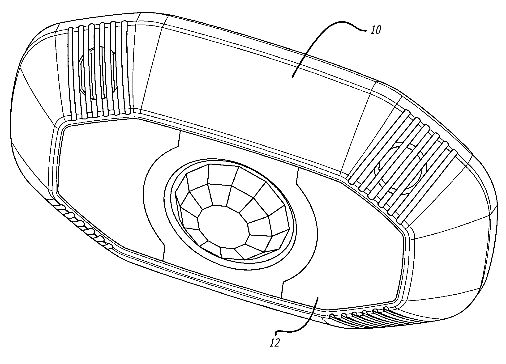
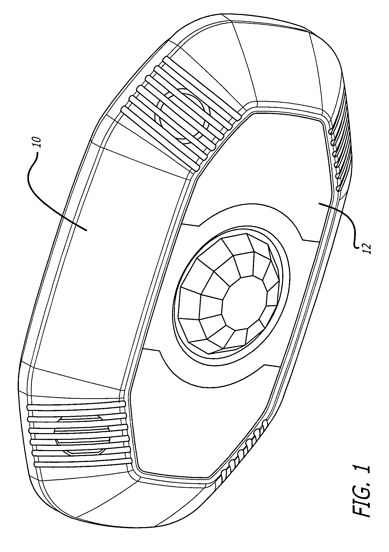
[0035]Referring to the drawings, in which like reference numerals refer to like or corresponding parts, the system 10 according to the invention provides reliable activation during occupancy of the covered area, and safeguards against false activation during vacancy of the area. The system 10 is able to activate upon sensing occupancy of the area, maintain activation when sensing continuing occupancy of the area, and enable self-adjusting of settings thereof.

[0036]FIG. 1 presents a system 10 which is utilized for the sensing of the occupancy and vacancy of the covered area. It includes an occupancy sensor 12, able to be installed for example in the ceiling of an area to be covered thereby such as a room in a building, and to be connected to a system to be controlled thereby such as a room lighting system. The occupancy sensor 12 is able to activate upon sensing the occupancy of the area, maintain activation when sensing continuing occupancy of the area, to enable settings therefor, ...


PUM


Abstract

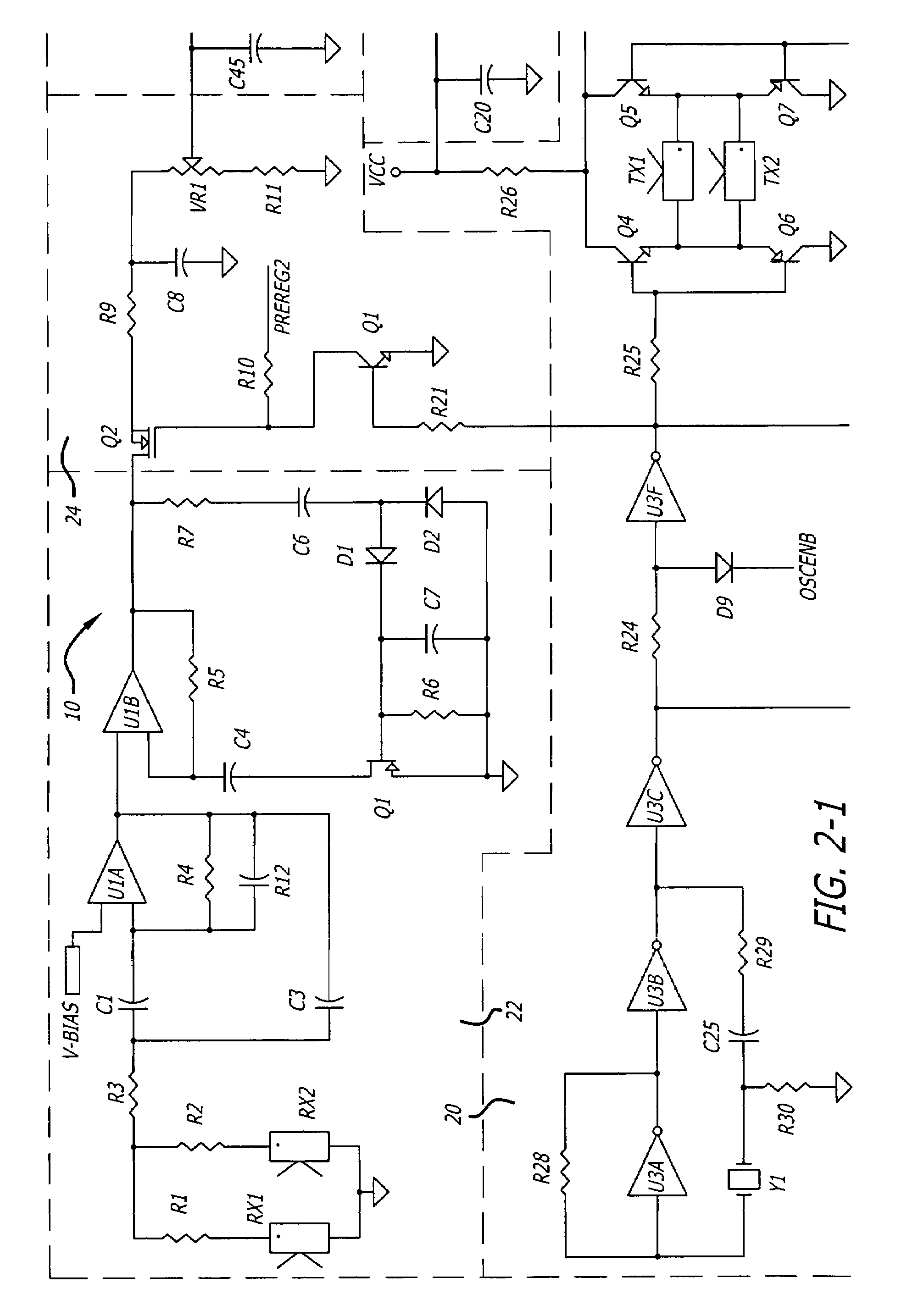
The present invention provides a system comprising an occupancy sensor for sensing occupancy of an area, able to activate upon sensing occupancy of the area, maintain activation when sensing continuing occupancy, to include settings therefor, and to enable self-adjusting of the settings. It includes an infrared sensor section, able to passively sense occupancy and activate a signal, continue to activate upon sensing continuing occupancy, and enable separate processing of the settings. It also includes an ultrasonic sensor section, able to actively sense occupancy, activate a signal upon sensing continuing occupancy, and enable separate processing of the settings. The occupancy sensor is able to activate when the infrared sensor section senses occupancy, and to maintain activation when either the infrared sensor section or the ultrasonic sensor section senses continuing occupancy of the area. The infrared sensor section signals and the ultrasonic sensor section signals are each independently formed and activated.

Description

CROSS-REFERENCE TO RELATED APPLICATION[0001]This application is a continuation of application Ser. No. 09 / 745,595 filed on Dec. 21, 2000 now abandoned, which claimed the benefit of a provisional application Ser. No. 60 / 173,528 filed on Dec. 29, 1999.COMPUTER PROGRAM LISTING APPENDIX[0002]A Compact Disc-Recordable (CD-R) which includes a computer program listing, and which was submitted with the parent application, is submitted with this application, since the computer program listing has over 300 lines of code. The material on the CD-R is incorporated by reference herein.[0003]A listing of all files contained in the compact discs enclosed herewith is as follows: machine format—IBM PC; operating system compatibility-Windows / DOS; name—Dual Tech Version 1, size—70,927 bytes, creation date—Sep. 16, 1999, type—assembly source code; name—Dual Tech Version 2, size—71,089 bytes, creation date—Nov. 18, 1999, type—assembly source code.BACKGROUND OF THE INVENTION[0004]1. Field of the Invention...

Claims


Application Information

Patent Timeline
IPC IPC(8): G08B23/00
CPCG08B13/1645G08B29/24G08B29/183G08B13/19
Inventor ELWELL, BRIAN E.HIMONAS, JAMES D.
Owner EATON INTELLIGENT POWER LIMITED
Learn More