In White et al., (U.S. Pat. No. 5,071,160) a single
acoustic sensor is described and, as illustrated, is disadvantageously mounted lower than the
steering wheel.
White et al. does not disclose where such sensors would be mounted, other than on the instrument panel below the
steering wheel, or how they would be combined to uniquely monitor particular locations in the passenger compartment and to identify the object(s) occupying those locations.
Such a combination, however, would not differentiate between an occupant with both hands and arms in the path of the ultrasonic
transmitter at such a location that they were blocking a substantial view of the occupant's head or chest.
As pointed out in one or more of the above-referenced patents and patent applications, direct occupant position measurement based on passive
infrared is probably not possible with a single
detector and, until very recently, was very difficult and expensive with
active infrared requiring the modulation of an expensive GaAs
infrared laser.
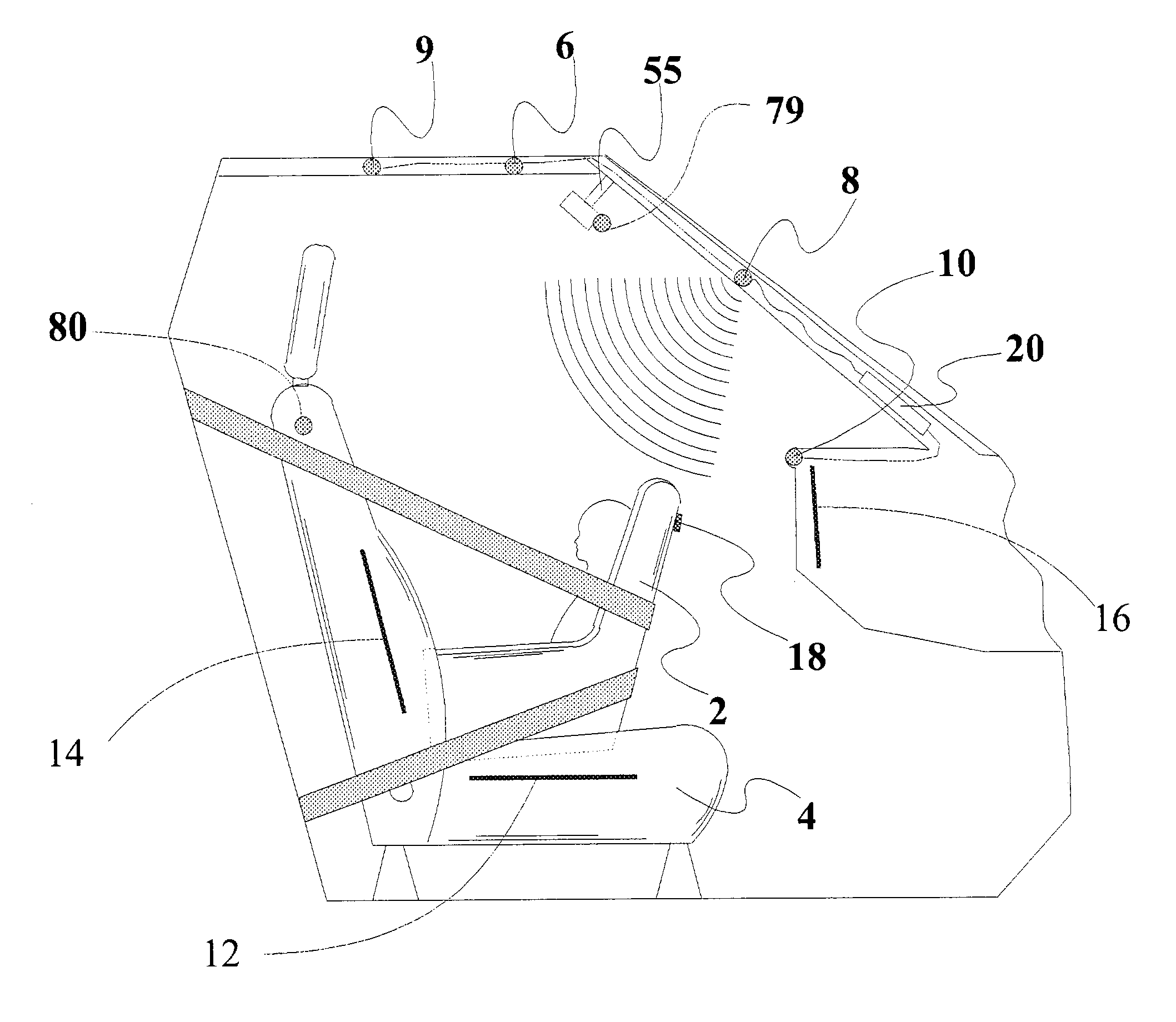
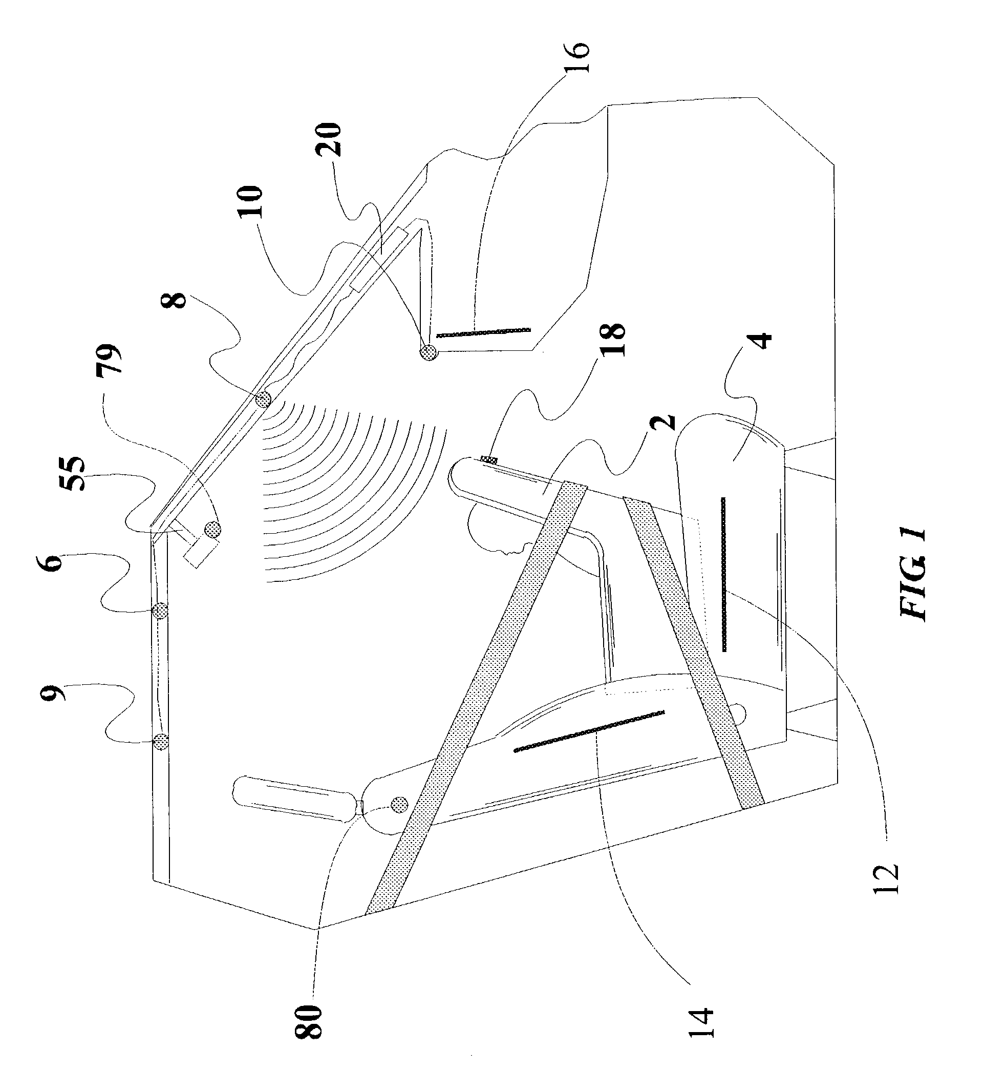
The object of an occupant out-of-
position sensor is to determine the location of the head and / or chest of the vehicle occupant in the passenger compartment relative to the occupant protection apparatus, such as an
airbag, since it is the
impact of either the head or chest with the deploying
airbag that can result in serious injuries.
Both such mounting locations are particularly prone to detection errors due to positioning of the occupant's hands, arms and legs.
In fact, the closer that the occupant gets to the
airbag, the faster the inflation rate of the airbag is according to the Fujita et al. patent, which thereby increases the possibility of injuring the occupant.
This combination can unnecessarily complicate the
processing of the data from the sensors and other
data processing methods can provide better results.
However, the
speed of sound limits the rate at which the position of the occupant can be updated to approximately 7 milliseconds, which though sufficient for most cases, is marginal if the position of the occupant is to be tracked during a vehicle
crash.
Secondly,
ultrasound waves are diffracted by changes in air density that can occur when the heater or air conditioner is operated or when there is a high-speed flow of air past the
transducer.
Thirdly, the resolution of
ultrasound is limited by its
wavelength and by the transducers, which are high Q tuned devices.
Finally, the fields from ultrasonic transducers are difficult to control so that reflections from unwanted objects or surfaces add
noise to the data.
The ultrasonic
system is the least expensive and potentially provides less information than the optical or
radar systems due to the delays resulting from the
speed of sound and due to the wave length which is considerably longer than the optical (including infrared) systems.
Also, it is sometimes difficult to discriminate the wave pattern of a normally seated child with the seat in a rear facing position from an empty seat with the seat in a more forward position.
In this case, the area covered is not as accurately controlled and a larger CCD or
CMOS array is required.
The
laser systems described above are expensive due to the requirement that they be modulated at a
high frequency if the distance from the airbag to the occupant, for example, needs to be measured.
A single camera is, naturally, the least expensive solution but suffers from the problem that there is no easy method of obtaining three-dimensional information about people or objects that are occupying the passenger compartment.
A second camera can be added but to locate the same objects or features in the two images by conventional methods is computationally intensive unless the two cameras are close together.
If they are close together, however, then the accuracy of the three dimensional information is compromised.
Since the
LED illumination is now more expensive than the imager, the cost of the second camera does not add significantly to the
system cost.
There is significant prior art on the use of a fisheye or similar high viewing angle lens and a non-moving pan, tilt, rotation and
zoom cameras however there appears to be no prior art on the application of these technologies to sensing inside or outside of the vehicle prior to the disclosure by the current assignee.
A focusing
system, such as used on some camera systems, can be used to determine the initial position of an occupant but, in most cases, it is too slow to monitor his position during a
crash.
A mechanical focusing system, such as used on some camera systems, can determine the initial position of an occupant but is currently too slow to monitor his / her position during a
crash or even during pre-crash braking.
Although the Subbarao patents provide a good discussion of the camera focusing art, it is a more complicated system than is needed for practicing the instant inventions.
Although each of these techniques is known to those skilled in the art, they have heretofore not been believed to have applied for monitoring objects within or outside of a vehicle.
However, if more than one
wavelength, or better one-quarter
wavelength, exists between the camera and the object, then ambiguities result.
There is no known prior art that places a filter in the
windshield.
There is no known prior art that places a pixel addressable filter in a
rear view mirror to selectively block glare or for any other purpose.
Also, the system only works if the particular person for whom the vehicle was programmed uses the coded object.
With the problems associated with the 4-way seats, it is unlikely that the occupant ever properly adjusts the seat.
Therefore, the error will be repeated every time the occupant uses the vehicle.
Prior art weight measurement systems have been notoriously inaccurate.
No attempt is made in any of these patents to locate the driver in the vehicle.
This technology could provide input data to a
pattern recognition system but it has limitations related to temperature.
The sensing of the child could
pose a problem if the child is covered with blankets, depending on the IR frequency used.
It also might not be possible to differentiate between a rear facing child seat and a forward facing child seat.
In all cases, the technology can fail to detect the occupant if the ambient temperature reaches body temperature as it does in hot climates.
Its main drawback is cost which is usually above that of ultrasonic or passive infrared systems.
It does not apply this technique for automotive applications and in particular for occupant sensing or monitoring inside or outside of a vehicle.
There is no known prior art for using natural
radiation for occupant sensing systems.
Once again, there is no known prior art for the use of color, for example.
Radar systems have similar properties to the
laser system discussed above except the ability to focus the beam, which is limited in
radar by the frequency chosen and the antenna size.
It is also much more difficult to achieve a scanning system for the same reasons.
The wavelength of a particular
radar system can limit the ability of the
pattern recognition system to detect object features smaller than a certain size.
Once again, however, there is some concern about the health effects of radar on children and other occupants.
Once again, there is not believed to be any prior art on the use of these imaging techniques for occupant sensing other than that of the current assignee.
However, it is difficult if not possible to measure these properties using static fields and thus a varying field is used which once again causes electromagnetic
waves.
Thus, the use of quasi-static low-frequency fields is really a limiting case of the use of
waves as described in detail above.
It cannot be produced by a steady distribution of electric charges.
However, this is not the case.
The Kithil system could not operate with a true static
electric field because a steady system does not carry any information.
However, such a system is not workable and thus Kithil reverts to a dynamic system using electromagnetic waves.
Thus, although Kithil declares the
coupling is due to a static
electric field, such a situation is not realized in his system because an alternating
electromagnetic field (“wave”) exists in the system due to the oscillator.
In some cases, the display is limited to information that would otherwise appear on the instrument panel.
This confuses the driver and in one study the driver actually performed worse than he would have in the absence of the
night vision information.
Such a system can be defeated if the driver is wearing glasses, particularly sunglasses, or another optical device which obstructs a clear view of his / her eyes.
Rather, Ando is limited to control of vehicle devices by responding to motion of the driver's mouth and eyes.
Again, Faris is only interested in locating the driver's eyes relative to the sun or oncoming headlights and does not identify or monitor the occupant or locate the occupant, a rear facing child seat or any other object for that matter, relative to the passenger compartment or the airbag.
Similarly, the implementation of the techniques of the above referenced patents requires expensive microprocessors while the implementation with neural networks and similar trainable pattern recognition technologies permits the use of low cost microprocessors typically costing less than $10 in large quantities.
Sometimes the data upon which the system is trained is sufficiently complex or imprecise that different views of the data will give different results.
In bright
daylight, however, unless the infrared illumination is either very bright or in the form of a scanning laser with a
narrow beam, the sun can overwhelm the infrared.
There is no known prior art on the use on neural networks, pattern recognition algorithms or, in particular, CANN for systems that monitor either the interior or the exterior of a vehicle.
There is no known prior art for continuous tracking systems to be used in data collection when adapting a system for monitoring the interior or exterior of a vehicle.
The prior art is limited to the preprocessing techniques of Ando, Chen and Faris for
eye detection and the
sensor fusion techniques of Corrado all discussed above.
Therefore, the direct use of the
optical correlation methods appears to be difficult and expensive.
This task could involve a contour extraction technique that does not require excessive computational effort but may have limited capabilities as to the reduction of redundancy.
One reason is the poor design of most seat adjustment systems particularly the so-called “4-way-seat”.
As a result, vehicle occupants are easily frustrated by such events as when the control to raise the seat is exercised, the seat not only is raised but is also rotated.
Occupants thus find it difficult to place the seat in the optimum location using this system and frequently give up trying leaving the seat in an improper driving position.
Without knowledge of the size of the occupant, the
lumbar support cannot be automatically adjusted.
Thus, many people are needlessly injured.
The danger of deployment-induced injuries will exist for
side impact airbags as they now do for frontal
impact airbags.
It is a problem in vehicles that children, infants and pets are sometimes left alone, either intentionally or inadvertently, and the temperature in the vehicle rises or falls.
Another problem relates to the theft of vehicles.
There have been incidents when a thief waits in a vehicle until the driver of the vehicle enters the vehicle and then forces the driver to provide the keys and exit the vehicle.
However, prior to the inventions disclosed herein engineers have not thought to determine the number, size and / or location of the occupants and use such determination in combination with the entertainment system.
The drawbacks include the lack of some important sensors of vehicle interior and environment condition (such as temperature or
air humidity).
It is not possible to set climate conditions individually at locations of each passenger seat.
Such systems are prone to errors caused by
dirt or ice in the window track, for example.
Prior art on window obstruction sensing is limited to the Prospect Corporation anti-trap system described in U.S. Pat. No. 5,054,686 and U.S. Pat. No. 6,157,024.
The
rear impact is the most expensive accident in America.
Once the system is operational, it would be logical for the system to also incorporate the airbag electronic sensor and diagnostics system (SDM) since it needs to interface with SDM anyway and since they could share computer capabilities, which will result in a significant cost saving to the auto manufacturer.
“Out-of-position” as used for an occupant will generally mean that the occupant, either the driver or a passenger, is sufficiently close to an occupant protection apparatus (airbag) prior to deployment that he or she is likely to be more seriously injured by the deployment event itself than by the accident.
It may also mean that the occupant is not positioned appropriately in order to attain the beneficial, restraining effects of the deployment of the airbag.

