Interphase for ceramic matrix composites reinforced by non-oxide ceramic fibers

a ceramic fiber and interphase technology, applied in the field of ceramic materials, can solve the problems of reducing the ability of each fiber to act independently, reducing the oxid reducing the oxidative impact so as to improve the oxidative durability of ceramic matrix composite materials, high composite strength, and reliable and more cost-effective

Active Publication Date: 2008-09-23
NASA UNITED STATES OF AMERICA AS REPRESENTED BY THE ADMINISTATOR OF THE
View PDF18 Cites 22 Cited by
  • Summary
  • Abstract
  • Description
  • Claims
  • Application Information

AI Technical Summary

Benefits of technology

[0009]The present invention seeks to improve the oxidative durability of ceramic matrix composite materials reinforced by non-oxide fibers in a more reliable and more cost-effective manner than prior art. To accomplish this, the present invention, in two embodiments, creates simple constituent and process conditions for composite fabrication that assure that the interphases are already outside debonded from the matrices in the as-fabricated materials. Even though the interphases are debonded, load transfer between the fibers and matrix and high composite strength are still maintained due to the complex fiber architectures which allow the interphases to mechanically slide against the matrix during the application of stress. Thus, when the material does crack, the complete interphase is retained on top of each fiber so that the oxidation can be reliably slowed from reaching the fiber. In comparison to prior art, this invention avoids the fabrication of complex interphase compositions and structures, does not rely on uncertain microstructural conditions for in-situ matrix crack deflection, and provides more reliable retention of the total interphase on the fiber surface.
[0010]According to one aspect of this invention, composite process and constituent conditions are disclosed which provide significant improvement for the oxidative durability of state-of-the-art SiC / SiC ceramic matrix composites after cracking in air at intermediate temperatures. The interphase material based on boron nitride (BN) compositions is allowed to debond from the SiC matrix (outside debonding) and remain on the SiC fiber surface after composite fabrication and during composite oxidation testing. The composite structural life is significantly enhanced over the normal situation where during testing of the same composite systems, the matrix cracks deflected inside the interphase (inside debonding), thereby allowing direct access of oxygen to the fiber surfaces.
[0011]Additionally, two exemplary embodiments, A and B, of the invention are disclosed. Both rely on the proper selection of constituent materials and composite fabrication processes in order to develop internal residual stresses during and after ceramic composite fabrication that eventually create outside debonded interphases in the finished composite product.

Problems solved by technology

However, the monolithic materials often fracture catastrophically and so fiber-reinforced composite materials are generally required for graceful failure and significantly improved toughness and damage tolerance.
One potential issue with non-oxide fibers is that if the ceramic matrix composite is cracked by unforeseen stresses, the crack-bridging fibers and their interphases will be exposed to oxidizing environments that enter the composite through matrix cracks that terminate at the composite surface.
However, although silica growth is slow, even a small amount can cause contacting fibers to bond to each other and to Si-based matrices, thereby eliminating the ability of each fiber to act independently.
The detrimental consequence is that if one fiber should fracture prematurely, all others to which it is bonded will fracture, causing catastrophic composite fracture or rupture at low stresses and short times. This oxidation issue for Si-based fibers typically begins at intermediate temperatures (600 to 800° C.) where the silica formation is slow but sufficient to cause fiber-fiber and fiber-matrix bonding.
However, all prior art patents related to the use of the outside debonding mechanism are based on the interphase debonding from the matrix to occur during matrix crack propagation, thus requiring similar microstructure conditions to exist locally near every interphase, even for complex fiber architectures produced by conventional textile processes.

Method used


Image

  • Interphase for ceramic matrix composites reinforced by non-oxide ceramic fibers
  • Interphase for ceramic matrix composites reinforced by non-oxide ceramic fibers
  • Interphase for ceramic matrix composites reinforced by non-oxide ceramic fibers

Examples


embodiment b

nding during composite processing due to thermally induced densification and contraction of the interphase

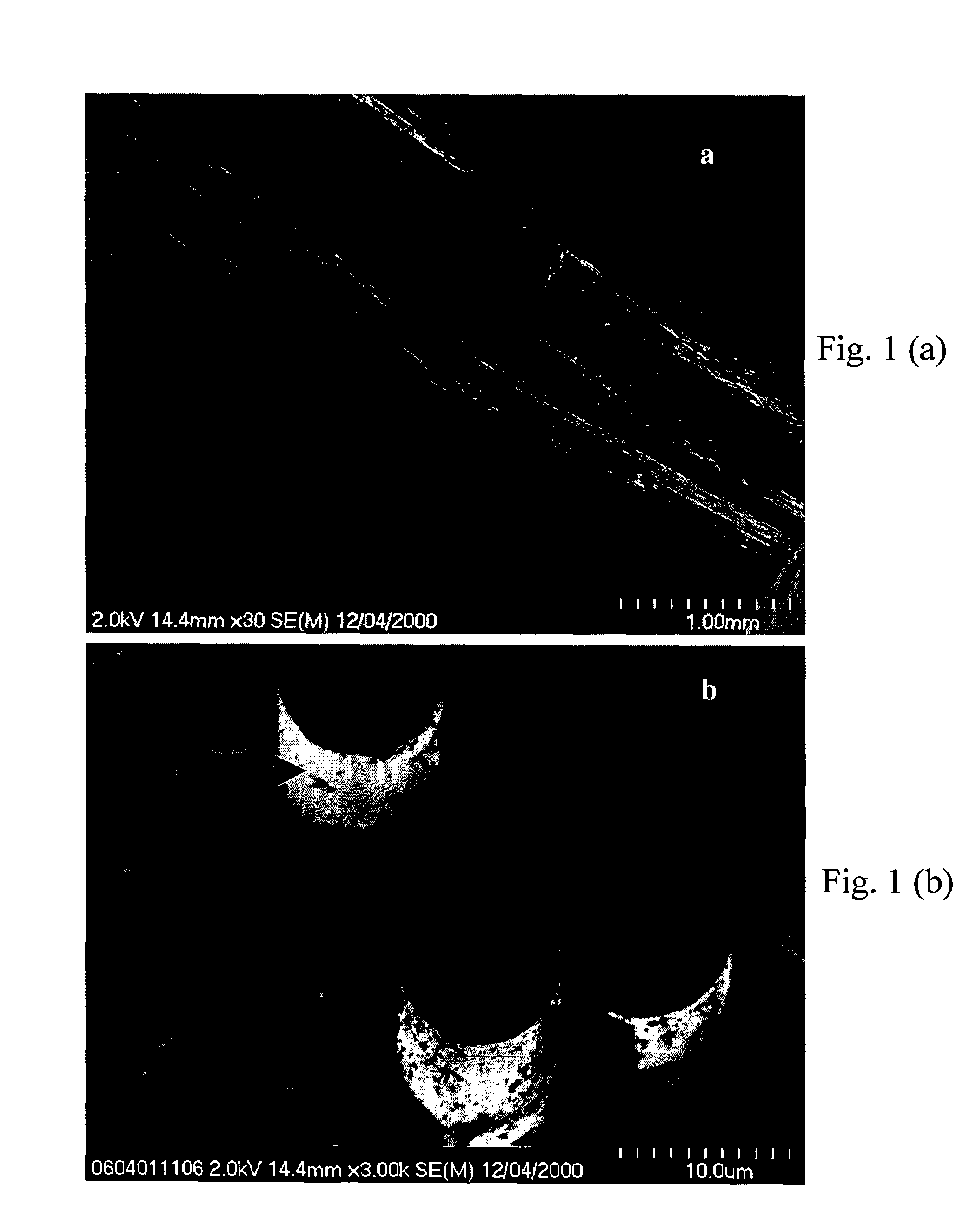
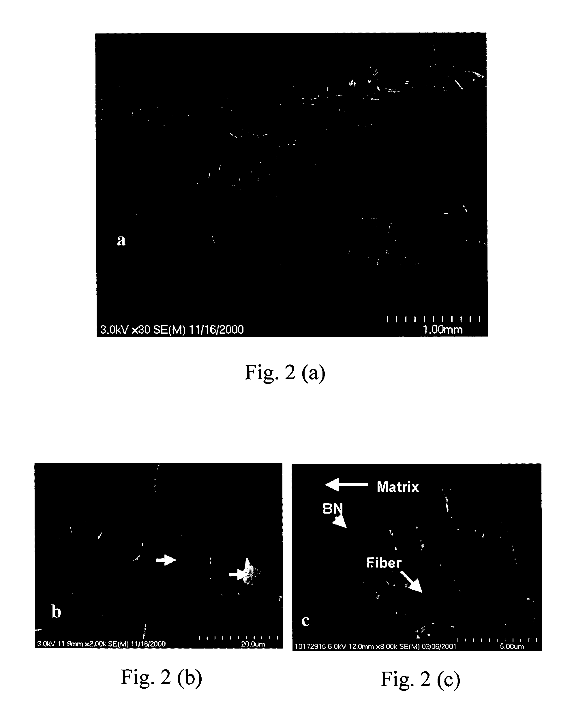
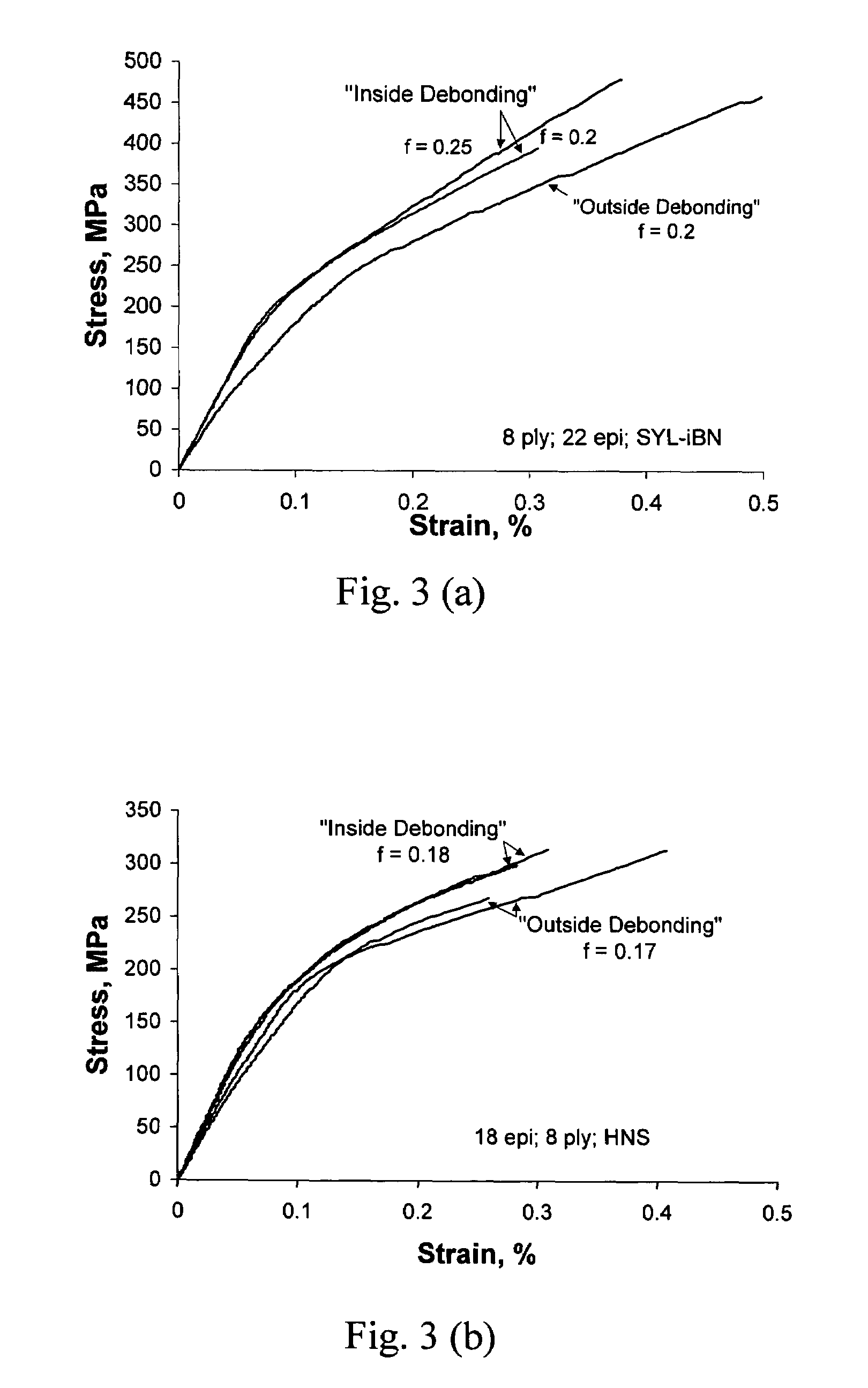
[0032]BN interphase deposition typically occurs at a temperature lower than the temperature typically employed for CVI SiC matrix formation (˜1000° C.), which in turn is lower than the maximum production temperatures for some near-stoichiometric SiC fiber types (>1600° C.). Thus, by exposing the BN interphase to CVI SiC process temperatures and even higher, significant shrinkage (sintering or densification) of the BN will occur due to crystallization and grain growth of the BN, but the microstructures of the near stoichiometric SiC fibers will remain stable. When this happens, the BN typically shrinks towards the fibers, thereby developing a tensile residual stress between the BN coating and CVI SiC matrix. Since the heat-treatment temperature controls the BN shrinkage, this innovation proposes to use temperatures high enough to create a sufficiently high tensile stress to cause...


PUM

PropertyMeasurementUnit
temperaturesaaaaaaaaaa

Abstract

A ceramic matrix composite material is disclosed having non-oxide ceramic fibers, which are formed in a complex fiber architecture by conventional textile processes; a thin mechanically weak interphase material, which is coated on the fibers; and a non-oxide or oxide ceramic matrix, which is formed within the interstices of the interphase-coated fiber architecture. During composite fabrication or post treatment, the interphase is allowed to debond from the matrix while still adhering to the fibers, thereby providing enhanced oxidative durability and damage tolerance to the fibers and the composite material.

Description

ORIGIN OF THE INVENTION[0001]The invention described herein was made by employees of the United States Government and may be manufactured and used by or for the Government for Government purposes without payment of any royalties thereon or therefore.BACKGROUND OF THE INVENTION[0002]1. Field of Invention[0003]The present invention relates to ceramic materials where the materials are ceramic matrix composites reinforced by continuous-length small-diameter ceramic fibers that are formed in complex shaped architectures by conventional textile processes. In particular, the present invention is based on improving the damage tolerance and oxidative durability of ceramic matrix composites consisting of non-oxide or oxide ceramic matrices reinforced by ceramic fibers with non-oxide chemical compositions.[0004]2. Description of Related Art[0005]As power and propulsion systems advance, there are many applications that require new materials that are expected to withstand high stresses for exten...

Claims


Application Information

Patent Timeline
Patent Type & Authority Patents(United States)
IPC IPC(8): B05D3/02B32B9/04C04B35/80D02G3/02
CPCC04B35/573C04B35/62868C04B35/62871C04B35/62873C04B35/62884C04B35/806C04B35/62894Y10T428/2918C04B2235/428C04B2235/5244C04B2235/80Y10T428/292C04B35/80C04B2235/3826C04B2235/614C04B2235/616C04B2235/79
Inventor DICARLO, JAMES A.BHATT, RAMAKRISHNAMORSCHER, GREGORY N.YUN, HEE-MANN
Owner NASA UNITED STATES OF AMERICA AS REPRESENTED BY THE ADMINISTATOR OF THE
Why Eureka
Try Eureka