
Droplet discharging head and microarray manufacturing method

a technology of microarrays and droplets, applied in the field of droplet discharging heads, can solve the problems of affecting channel performance, reducing discharge performance, and losing the activity of protein origin, and achieve the effects of stable spot shape, high density, and rapid formation

Inactive Publication Date: 2008-10-21
KAZUHIKO ISHIHARA +1
View PDF13 Cites 38 Cited by
  • Summary
  • Abstract
  • Description
  • Claims
  • Application Information

AI Technical Summary

Benefits of technology

The present invention provides a droplet discharging head that can be used with bio-related substances without damaging them. The head has a polymer covering the inner walls of the droplet discharging channels, which prevents adsorption of the sample solution to the inner walls and maintains the concentration of the sample solution. The droplet discharging head is preferably an electrostatic or piezoelectric drive type, which does not generate heat and allows for stable discharge on a solid phase surface. The invention also provides a method for manufacturing the droplet discharging head and a microarray with the head.

Problems solved by technology

However, proteins are used as the probe in the production of protein chips, but when a solution containing protein is used in an inkjet head, the protein may adsorb (adhere) to the inner walls of the inkjet head, which can markedly affect channel performance and therefore diminish discharge performance.
Another result of this adsorption (adhesion) to the inner walls of the inkjet head is that the concentration of the sample solution may be inconsistent, and the protein structure itself may change, resulting in a lost of the activity which the protein has originally.

Method used


Image

  • Droplet discharging head and microarray manufacturing method
  • Droplet discharging head and microarray manufacturing method
  • Droplet discharging head and microarray manufacturing method

Examples


example 1

Readying a Droplet Discharging Head

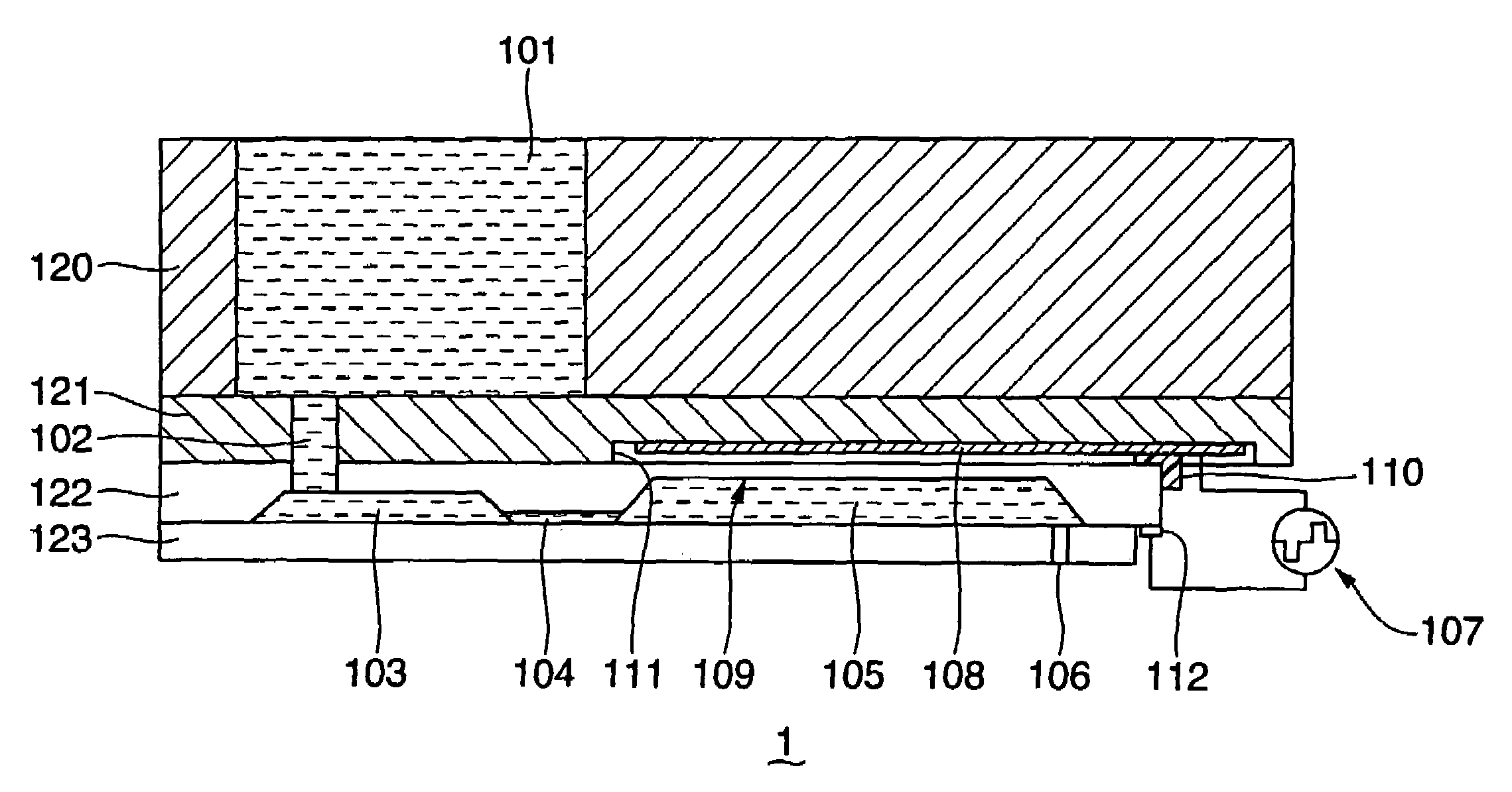
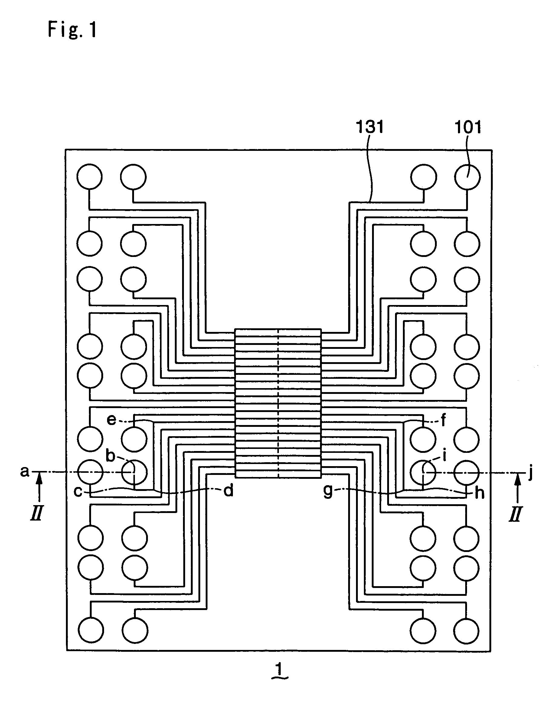
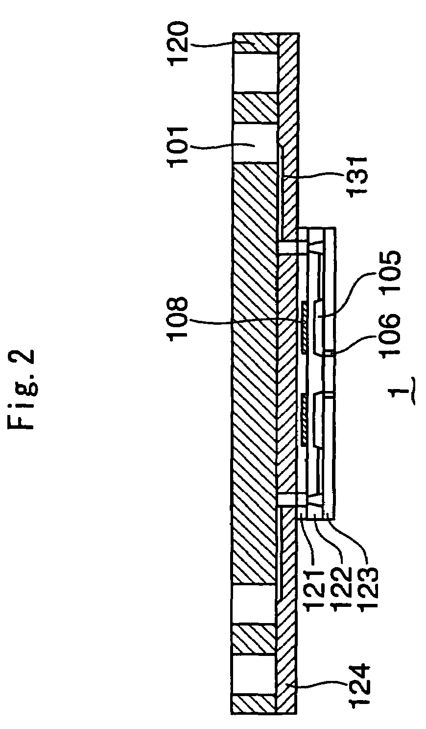
[0095]The droplet discharging head shown in FIG. 1 was readied.

[0096]Silicon was used for the pressurization chamber substrate and nozzle substrate, borosilicate glass was used for the electrode substrate, and PMMA (a methacrylic resin) was used for the reservoir component.

Preparation of coating solution:

[0097]A copolymer of MPC and MPTMS (3-methacryloylpropyltri-methoxysilane) with a molar ratio of 9:1 was readied (hereinafter referred to as MPC-MPTMS copolymer). This MPC-MPTMS copolymer was dissolved in ethanol to prepare a 0.1% ethanol solution.

[0098]The MPC-MPTMS copolymer was manufactured by the following method. The MPC was made by NOF Corporation, while the MPTMS was made by Shin-Etsu Silicone.

[0099]Specific amounts of MPC and MPTMS were each dissolved in 5 mL of ethanol, after which these solutions were mixed so that the monomer ratio would be 90 / 10, and this mixture was diluted with ethanol so that the total monomer concentration would be ...


PUM

PropertyMeasurementUnit
angleaaaaaaaaaa
thicknessaaaaaaaaaa
thicknessaaaaaaaaaa

Abstract

It is an object of the present invention to provide a droplet discharging head suited to the discharge of a sample solution, and particularly one that contains a bio-related substance. This object is achieved by a droplet discharging head 1 for discharging a sample solution, wherein the portion of the inner walls of the droplet discharging head 1 that comes into contact with the sample solution is covered with a polymer composed of phosphorylcholine group-containing unsaturated compound units, or a copolymer including same. The droplet discharging head is preferably an electrostatic drive or piezoelectric drive type.

Description

BACKGROUND OF INVENTION[0001]1. Field of the Invention[0002]The present invention relates to a droplet discharging head, and more particularly relates to a droplet discharging head suited to the discharge of a bio-related substance.[0003]2. Description of the Related Art[0004]The decoding of DNA base sequences and the functional analysis of genetic information have become topics of great interest in recent years, and DNA microarrays have been utilized for monitoring gene expression patterns and for screening new genes. With these arrays, probe DNA is prepared and spotted at high density on a substrate such as a slide glass, after which the portion of fluorescent-labeled target DNA having base sequences that are compatible with the probe DNA is hybridized and the fluorescent pattern is observed, which gives an evaluation of the amount of gene expression. The size of these arrays is usually from 1 to 10 cm2, and from several thousand to several tens of thousands of types of probe DNA ...

Claims


Application Information

Patent Timeline
Patent Type & Authority Patents(United States)
IPC IPC(8): B01L3/02G01N33/53B41J2/14B41J2/16G01N35/10G01N37/00
CPCB01L3/0268B41J2/14314B41J2/1433B41J2/1606B01L2200/021B01L2300/0809B01L2300/0819B01L2300/163B01L2400/0415B01L2400/0439
Inventor TAKAGI, FUMIOISHIHARA
Owner KAZUHIKO ISHIHARA
Learn More