Variable capacitor and manufacturing method thereof

a manufacturing method and variable capacitor technology, applied in variable capacitors, capacitors with electrode area variation, fixed capacitors, etc., can solve the problems of dielectric loss, inability to change the electrostatic capacity of the voltage, and the voltage variation of the voltage variation capacitor, so as to prevent the energy loss of the input signal, reduce the distance between the electrodes, and remove the kind of reflected signal

Active Publication Date: 2008-11-04
FUJITSU LTD
View PDF16 Cites 11 Cited by
  • Summary
  • Abstract
  • Description
  • Claims
  • Application Information

AI Technical Summary

Benefits of technology

[0009]The inventors have proposed a variable capacitor that is constructed with two opposing electrodes that are both driven by a piezoelectric actuator (Japanese patent application Laid-Open No.2004-127973). In this kind of variable capacitor having two movable electrodes, there is no solder bumps, so it is possible to easily decrease the distance between both of these electrodes, and even though the capacitor may be small, it is possible to obtain large electrostatic capacity, and it is possible for the electrostatic capacity to change a large amount.
[0079]In this way, with this fifth embodiment, two-stage distance control is performed by the piezoelectric-actuator drive and electrostatic-actuator drive, making it possible to bring the movable electrodes even closer together, and thus making it possible to obtain even larger change in electrostatic capacity. After the movable electrodes have been brought close together by the piezoelectric actuator, electrostatic attraction occurs, which has the effect of making it possible to obtain large electrostatic capacity and change in capacity. Moreover, after the movable electrodes have been brought close together by the piezoelectric actuator, electrostatic attraction occurs, so it is possible to generate large electrostatic attraction with a small drive voltage.

Problems solved by technology

However, the conventional variable capacitor described above has problems as described below.
Therefore, the fact that it is not possible for the electrostatic capacity in the initial state to become large (it remains small) also means that it is not possible for the change in electrostatic capacity to become large (it remains small).
The narrow torsion bar 17 is included in the line to the movable electrode 13 of the capacitor, so there is a problem in that this portion forms equivalent series resistance (ESR) and resistance loss occurs; also, the signal line that is electrically connected to the variable capacitor also functions as the drive electrode for the piezoelectric actuator 12, so when this signal line comes in contact with the dielectric piezoelectric element, there is a problem in that dielectric loss occurs, and the Q value becomes very small.

Method used


Image

  • Variable capacitor and manufacturing method thereof
  • Variable capacitor and manufacturing method thereof
  • Variable capacitor and manufacturing method thereof

Examples


first embodiment

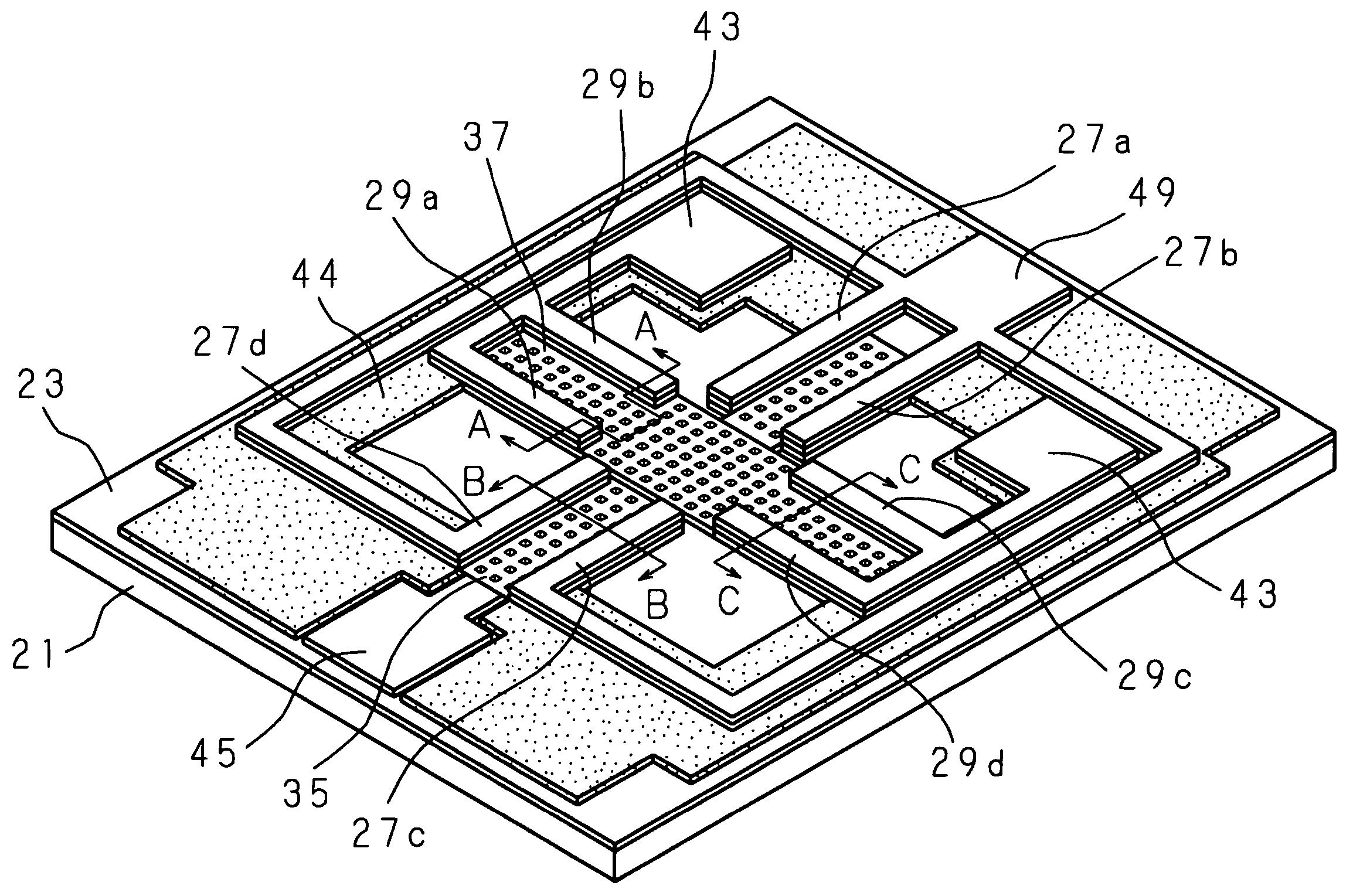
[0040]FIG. 3 is a pictorial view of the variable capacitor of a first embodiment of the present invention, and FIG. 4 is an exploded pictorial view of the same. In the figure, 21 is a substrate that is formed using a compound semiconductor. A cross-shaped opening 40 is formed in the center section of that substrate 21, and an insulating layer 23 is formed on the top surface of the substrate 21.

[0041]In the figure, 35 is a lower movable electrode and 37 is an upper movable electrode, where both are made of aluminum (Al). The lower movable electrode 35 comprises line sections 35a, 35a on both ends to form a first electrode section, and a central capacitor section 35b to form a second electrode section, where the end section of one of the line sections 35a is connected to a signal pad 45 to which a signal is inputted from an external high-frequency-signal source (not shown in the figure), and the end section of the other line section 35a is connected to the insulating layer 23 and is e...

second embodiment

[0057]FIG. 10 is an exploded pictorial view of the variable capacitor of a second embodiment of the invention, and FIG. 11 and FIG. 12 are cross-sectional drawings showing the manufacturing process for this variable capacitor.

[0058]In this second embodiment, there is a space 50 around the lower movable electrode 35, upper movable electrode 37, lower-movable-electrode actuator 27 and upper-movable-electrode actuator 29 between the lower movable electrode 35, upper movable electrode 37 and insulating layer 23 and the substrate 21. Also, instead of being made of silicon, the substrate 21 is formed from a material such as glass, sapphire, alumina, glass ceramic, gallium arsenic, or the like. The remaining construction is the same as that of the first embodiment, and the same reference numbers are given to identical sections.

[0059]After forming a second sacrificial layer 51 made from silicon using a sputtering method on top of the substrate 21 that is made from a material such as glass, ...

third embodiment

[0063]FIG. 13 is an exploded pictorial view of the variable capacitor of a third embodiment of the invention (only the movable electrode and actuator), and FIG. 14 and FIG. 15 are cross-sectional drawings showing the manufacturing process for this variable capacitor.

[0064]In this third embodiment, a dielectric layer 46 is located between the lower movable electrode 35 (capacitor section 35b) and the upper movable electrode 37 (capacitor section 37b). The other construction is the same as that of the first embodiment, and the same reference numbers are given to identical sections and an explanation is omitted.

[0065]This dielectric layer 46 can be located on the side of the upper movable electrode 37 (capacitor section 37b) as shown in FIG. 13, or on the side of the lower movable electrode 35 (capacitor section 35b) (not shown in the figure). The mass of the movable section is increased by using this dielectric layer 46, so the resonant frequency is slightly lowered or the movement sp...


PUM


Abstract

A lower movable electrode 35, having line sections 35a, 35a on both ends and a capacitor section 35b in the center, and an upper movable electrode 37, having line sections 37a, 37a on both ends and a capacitor section 37b in the center, are placed so that the capacitor sections 35b, 37b face each other, and drive electrodes of lower-movable-electrode actuators 27a, 27b, 27c, 27d driving the lower movable electrode 35 and upper-movable-electrode actuators 29a, 29b, 29c, 29d driving the upper movable electrode 37 are electrically separated from the lower movable electrode 35 and upper movable electrode 37. These actuators 27a to 27d and / or 29a to 29d move the lower movable electrode 35 and / or upper movable electrode 37 to adjust the distance between both capacitor sections 35b, 37b, and control the electrostatic capacity.

Description

[0001]This application is a Continuation Application of international Application no. PCT / JP2004 / 007493, filed May 31, 2004, the entire specification claims and drawings of which are incorporated herewith by reference.TECHNICAL FIELD[0002]This invention relates to a variable capacitor and manufacturing method thereof, and more particularly to a variable capacitor, which uses MEMS (Micro Electro Mechanical System) technology and has opposing movable electrodes, and manufacturing method thereof.BACKGROUND ART[0003]A variable capacitor is an important part in electrical circuits such as a variable frequency oscillator, tuned amplifier, phase shifter, impedance-matching circuit and the like, and in recent years, use in portable devices has been increasing. In comparison with varactor diodes that are mainly used now, variable capacitors that are manufactured using MEMS technology have the advantage of less loss and higher Q value, therefore development is rapidly advancing.[0004]FIG. 1(a...

Claims


Application Information

Patent Timeline
Patent Type & Authority Patents(United States)
IPC IPC(8): H01G5/01H01G5/011H01G5/015H01G5/16
CPCH01G5/011H01G5/16H01G5/015
Inventor SHIMANOUCHI, TAKEAKIIMAI, MASAHIKONAKATANI, TADASHI
Owner FUJITSU LTD
Why Eureka
Try Eureka