Fluorescence observation equipment

a fluorescence observation and equipment technology, applied in the direction of optical radiation measurement, force measurement by measuring optical property variation, spectral modifiers, etc., can solve the problems of poor fluorescence pick-up efficiency, bad emission filter and absorption filter, no use, etc., to achieve high fluorescence intensity and bright image observation

Inactive Publication Date: 2008-11-18
EVIDENT CORP
View PDF13 Cites 21 Cited by
  • Summary
  • Abstract
  • Description
  • Claims
  • Application Information

AI Technical Summary

Benefits of technology

[0028]According to the present invention, in an apparatus for fluorescence observation using an excitation filter and an absorption filter, or using laser light and an absorption filter, an apparatus for fluorescence observation by which weak fluorescence can be picked up efficiently and a high sensitive fluorescence intensity measurement with bright image observation can be obtained.

Problems solved by technology

However, so far, because the performance of the excitation filter and the absorption filter are bad, fluorescence has not been picked up efficiently.
Since such light in this wavelength range of about 20 nm has not been used as fluorescence or as exciting light, there is a problem that it has been of no use.
This problem is also the same when using laser light as illumination light.
That is, since light within a wavelength width between “a wavelength of laser light” and “a half-value wavelength at the short-wavelength side of the absorption filter” has not been used as fluorescence or as exciting light, there was a problem that it has been of no use.

Method used


Image

  • Fluorescence observation equipment
  • Fluorescence observation equipment
  • Fluorescence observation equipment

Examples


first embodiment

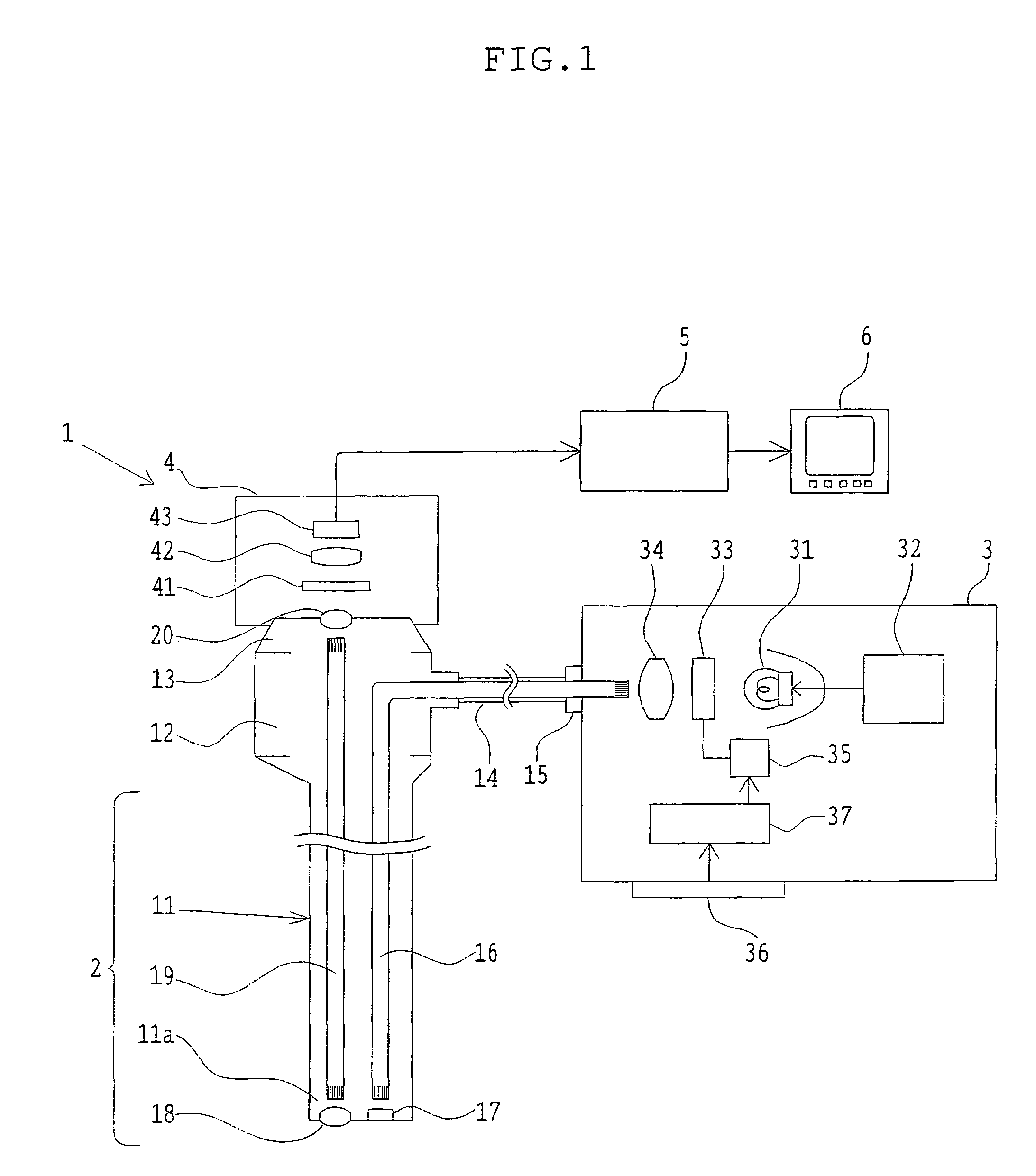
[0062]FIG. 1 is an outline composition diagram of an endoscope for medical treatments for diagnosing existence of a disease of an organism etc, by carring out fluorescence observation and its optical system of the first embodiment of the apparatus for fluorescence observation according to the present invention.

[0063]This apparatus for fluorescence observation 1, comprises, as shown in FIG. 1, an endoscope 2 which is inserted into an abdominal cavity etc., and obtains an observation image of a tissue for observation, a light source 3 which supplies an illumination light to the endoscope 2, an image pick-up apparatus 4 which picks up the observation image obtained with the endoscope 2, and obtains an image pick-up signal, and a video processor 5 which changes the image pick-up signal acquired by the image pick-up apparatus 4 into the picture signal in which a monitor display is possible, and a monitor equipment 6 which shows the picture signal obtained by the video processor 5.

[0064]T...

second embodiment

[0104]FIG. 8 is an outline composition diagram of an optical system of a fluorescence intensity measuring instrument concerning the second embodiment of the apparatus for fluorescence observation according to the present invention.

[0105]In the optical system shown in FIG. 8, an optical path of laser light 51 having wavelength of 488 nm and intensity of 800 mW which is emanated from a laser source that is not illustrated, is bent as exciting light by the mirror 52, and then it is irradiated to the specimen 53 on a specimen installation stand 53a. In an absorption filter 54, only the fluorescence generated from the specimen 53 transmits selectively. This system is constructed such that fluorescence can be observed by measuring the intensity of this fluorescence by CCD and a light receiving portion 55 which has a function of displaying a signal after a signal detected by CCD has been converted to an electric current value.

[0106]As for the absorption filter 54, a filter having a similar...

third embodiment

[0109]The excitation filter 33 and the absorption filter 41 in the first embodiment were replaced by a filter which has a characteristic shown in a graph showing a relation between the wavelength and the transmittance of the filter in FIG. 9.

[0110]A half-value wavelength at a long-wavelength side of the excited filter 33 is 459.5 nm and a half-value wavelength at a short-wavelength side of the absorption filter 41 is 462.8, and the wavelength width which is an interval of these is 3.3 nm.

[0111]Characteristic of each filter will be explained more in detail based on the graph (characteristic diagram) of FIG. 9. The excitation filter 33 has a transmittance characteristic such that the range of the half-value wavelength where a transmittance becomes as a half of the maximum value (50%) is 433.4˜459.5 nm and the wavelength range where a transmittance becomes 0.1% or less is 300 nm˜421.1 nm and 460.4 nm˜1000 nm, and a wavelength range where a transmittance becomes 80% or more is 435.7 nm˜...


PUM

PropertyMeasurementUnit
widthaaaaaaaaaa
wavelengthaaaaaaaaaa
half-value wavelengthaaaaaaaaaa

Abstract

An apparatus for fluorescence observation includes an excitation filter which transmits only exciting light of an specific wavelength among illumination light, and an absorption filter which blocks the exciting light and transmits only fluorescence generated from a specimen when the exciting light is irradiated to the specimen. Here, an interval of a half-value wavelength at a long-wavelength side of the excitation filter and a half-value wavelength at a short-wavelength side of the absorption filter is in a width between 1 nm to 6 nm, and change of the half-value wavelength of the excitation filter and the absorption filter when humidity changes from 10% to 95%, is 0.5 nm or less.

Description

[0001]This is a 371 national phase application of PCT / JP2004 / 006733 filed 19 May 2004, claiming priority to Japanese Patent Applications No. 2003-181614 filed 25 Jun. 2003, No. 2003-316995 filed 9 Sep. 2003, and No. 2004-109327 filed 1 Apr. 2004, the contents of which are incorporated herein by reference.TECHNICAL FIELD[0002]The present invention relates to an apparatus for fluorescence observation, such as a microscope and an endoscope which are used for fluorescence observation, and a measuring instrument for measuring an intensity of fluorescence.BACKGROUND ART[0003]So far, fluorescence observation using a microscope, an endoscope, etc. as an apparatus for the fluorescence observation, wherein exciting light is illuminated to a specimen of a living tissue etc., and only the fluorescence generated from the specimen is used, has been carried out.[0004]In order to carry out this fluorescence observation, as for an apparatus for the fluorescence observation as a mechanism for fluores...

Claims


Application Information

Patent Timeline
Patent Type & Authority Patents(United States)
IPC IPC(8): G01J3/30F21V9/16A61B1/00A61B1/04A61B5/00G01N21/64G02B5/22G02B5/28G02B21/06G02B21/16G02B23/24G02B23/26
CPCA61B1/043A61B5/0071A61B5/0084G01N21/6458G02B21/16A61B1/042G02B5/285G02B23/2469G02B23/26
Inventor KAWAMATA, KENTOYOHARA, NOBUYOSHI
Owner EVIDENT CORP
Why Eureka
Try Eureka