Signal conditioning methods and circuits for a capacitive sensing integrated tire pressure sensor

a capacitive sensor and integrated tire pressure sensor technology, applied in the field of electronic circuits, can solve the problems of large capacitors, low circuit power consumption, and large capacitive sensors, and achieve the effect of reducing errors

Active Publication Date: 2008-11-25
SAMSUNG ELECTRONICS CO LTD
View PDF15 Cites 52 Cited by
  • Summary
  • Abstract
  • Description
  • Claims
  • Application Information

AI Technical Summary

Problems solved by technology

The capacitive sensor is often accompanied by large, unwanted parasitic load capacitors.
These parasitic capacitors can easily inundate the sensor capacitors, resulting in attenuation of the measured signal.
Further, in the case of a battery-powered tire pressure measurement system, very low circuit power consumption is required.

Method used


Image

  • Signal conditioning methods and circuits for a capacitive sensing integrated tire pressure sensor
  • Signal conditioning methods and circuits for a capacitive sensing integrated tire pressure sensor
  • Signal conditioning methods and circuits for a capacitive sensing integrated tire pressure sensor

Examples


embodiment 600

[0047]The circuit of FIG. 6 shows a reverse sensor circuit embodiment 600 of the invention that includes operating the sensor circuit with the MEMS sensor 104 reversed. This circuit requires the addition of a double-frequency clocking scheme. The sensor capacitors (402, 404) are sampled at twice the frequency in which the sigma-delta converter 610 operates, where the sigma delta converter is shown within dashed brackets. The clocks Φ3 and Φ4 (not shown) are the double frequency clocks, whereas Φ1 and Φ2 are the base frequency clocks (not shown). During Φ1, sensor capacitor C1402 is sampled, amplified, and the result is stored on integrator capacitor C3602. During Φ2, sensor capacitor C2404 is sampled and amplified, and the result is stored on integrator capacitor C4604. At the end of Φ2, when both capacitor samples have been stored in the first stage integrator 606 sample-capacitors (602, 604), the integrator 606 processes the data, and passes the result on to the second integrator ...

embodiment 800

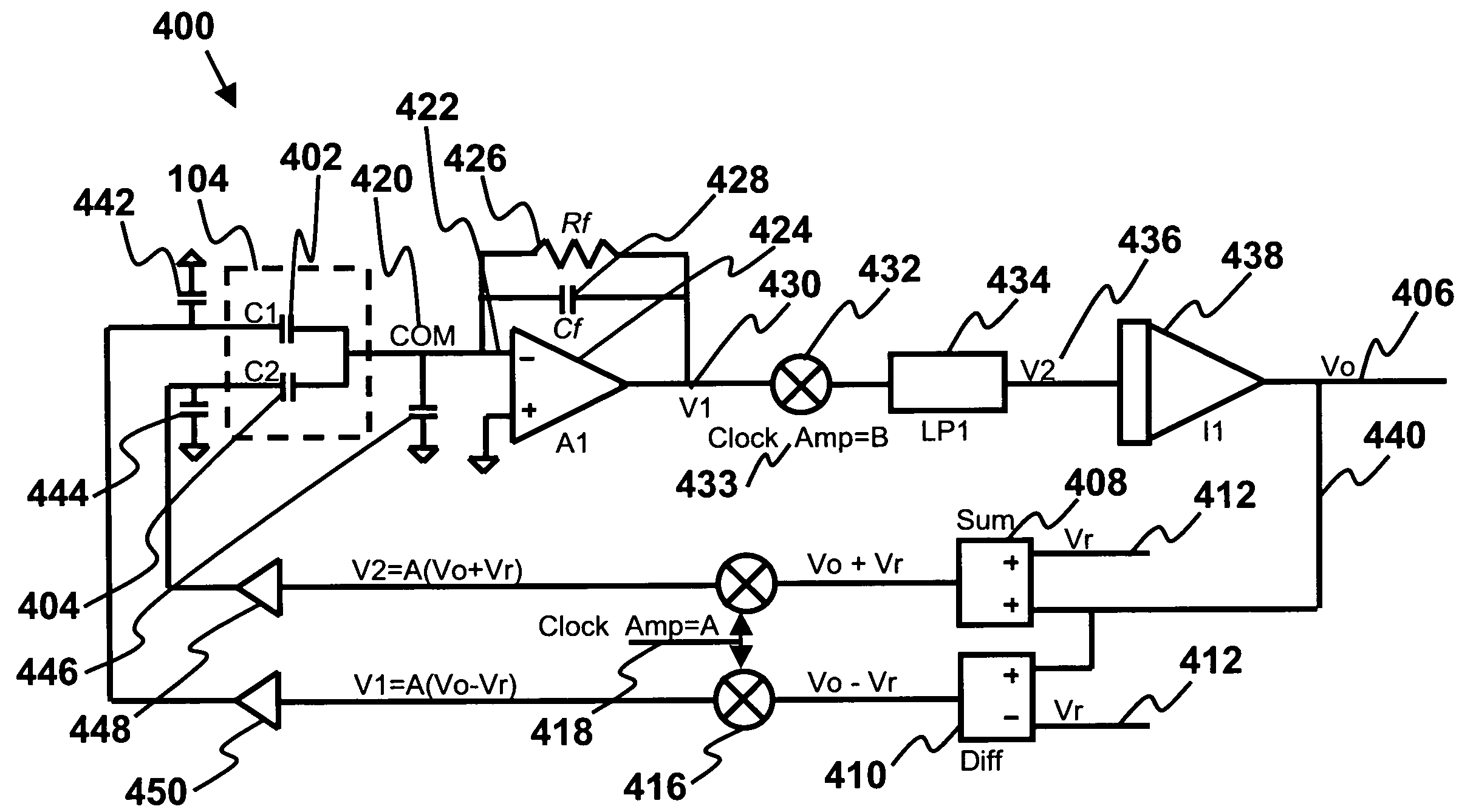
[0052]An improved signal to noise ratio embodiment 800 is shown in FIG. 8 according to the current invention. In this circuit, there are two amplifiers that process the sensor capacitance information—a differential amplifier 802, and a sum amplifier 804. These two amplifiers take turns sampling the sense capacitors (402, 404), where when one is active, the output of the other is held constant. The difference amplifier output 806 is applied an input 808 of the Analog to Digital Converter (ADC) 810, and the sum amplifier output 812 is applied to the reference input 814 of the ADC 810. The difference amplifier output 806 is given by:

[0053]Vout⁡(Diff)=Vd⁢(C⁢⁢1-C⁢⁢2)Cd⁢⁢1Equation⁢⁢9

where Cd1816 is a precision on-chip capacitor, which is typically a poly-poly capacitor, or a MIM (metal-insulator-metal) capacitor, and Vd 818 is the drive voltage, which may be the power supply voltage.

[0054]The sum amplifier output 812 is given by:

[0055]Vout⁡(Sum)=Vd⁢(C⁢⁢1+C⁢⁢2)Cd⁢⁢2Equation⁢⁢10

where Cd2820...

embodiment 1100

[0067]According to the multi-cycle correction voltage embodiment 1100 shown in FIG. 11, A21102 is the differential amplifier, and A11104 is a common mode correction integrator. During Φ1 clock cycle, A21102 is reset, and A11104 is isolated from A21102. The output of integrator A11104 is sampled onto the two common mode correction capacitors Ccm11106 and Ccm21108. During the Φ2 amplify cycle A21102 amplifies the difference between C1402 and C2404. The voltage that was previously placed on Ccm11106 and Ccm21108 is applied to the common mode input VCM 1110, and corrects the common mode voltage. This corrected voltage is also sampled onto Cs11112 and Cs21114. If the correction was perfect, then this voltage will be zero. If not, then these capacitors (1112, 1114) hold the error signal. On the subsequent cycle, the error voltage on Cs11112 and Cs21114 is integrated on A11104, to reduce the error. When the loop has stabilized, the output 1116 of A11104 will be exactly the correct voltage ...


PUM


Abstract

A tire pressure monitoring system is provided that includes a switched capacitor circuit having a clock with two non-overlapping clock phases that control a state of analog switches of the switched capacitor circuit. The system uses tire pressure sensor MEMS capacitors that are measured differentially. A capacitance-to-voltage converter is connected to the MEMS sense capacitor, and a sigma-delta converter having a comparator with a first digital output state and a second digital output state is used. The first output state is a sum of reference voltages and the second output state is a difference of the reference voltages. An average value of the capacitance-to-voltage converter output is driven to a zero value and a digital output is provided of the average output states that is equal to a difference between the MEMS capacitors divided by their sum multiplied by a ratio of the reference voltages.

Description

CROSS-REFERENCE TO RELATED APPLICATIONS[0001]This application is cross-referenced to and claims the benefit from U.S. Provisional Patent Application 60 / 819,824 filed Jul. 10, 2006, which is hereby incorporated by reference.FIELD OF THE INVENTION[0002]The invention relates generally to electronic circuits. More particularly, the invention relates to electronic circuits for signal conditioning and power management of differential-capacitive sensors for integrated tire pressure sensors.BACKGROUND[0003]A capacitive pressure sensor, or capacitive accelerometer, conveys the state of the pressure measurement by varying the magnitude of its capacitance. An electronic circuit must be used to measure this changing capacitance. Typically, the magnitude of the capacitance change is very small, while the required resolution is quite high, often as high as 16-bits (one part in 65,535). The capacitive sensor is often accompanied by large, unwanted parasitic load capacitors. These parasitic capacit...

Claims


Application Information

Patent Timeline
Patent Type & Authority Patents(United States)
IPC IPC(8): B60C23/02H03M1/12
CPCB60C23/0408G01L9/12
Inventor SKURNIK, DAVID
Owner SAMSUNG ELECTRONICS CO LTD
Why Eureka
Try Eureka