
Particle counter with improved image sensor array

a technology of image sensor array and particle counter, which is applied in the field of particle counter with improved image sensor array, can solve the problems of background noise, inability to detect all the particles in the fluid of interest, and very different operation principles of particle counters, and achieve the effect of increasing the signal-to-noise ratio

Active Publication Date: 2008-11-25
PARTICLE MEASURING SYST
View PDF7 Cites 40 Cited by
  • Summary
  • Abstract
  • Description
  • Claims
  • Application Information

AI Technical Summary

Benefits of technology

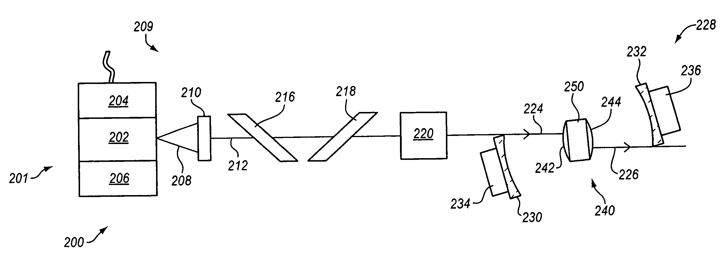
The present invention provides an optical particle counter that includes a CMOS imager array for detecting unconstrained particles of less than one micron in size in a flowing fluid. The counter uses a multiple beam laser optical system to provide a plurality of laser beams in the sample chamber, which are redirected back through the sample chamber once to detect the scattered light. The optical detector has a sensing region with a cross-sectional area of 0.5 square millimeters or more. The invention helps to overcome the problems of optical particle counters by providing an improved method for detecting unconstrained particles in a flowing fluid.

Problems solved by technology

These latter systems rely on collecting scattered light from millions, billions, and more particles; therefore, their principles of operation are very different from the principles used in particle counters.
Generally, it is not possible to detect all the particles in the fluid of interest, since the amount of fluid is quite large.
Another constraint that must be taken into account in particle counting is the background noise due to scattering of light by the molecules of the fluid in which the contaminant particles are contained.
While the amount of light scattered by each molecule of fluid is small, the number of fluid particles is extremely large.
The light scattered by the fluid molecules cannot be eliminated.
However, the design was not successful and never became a commercial product.
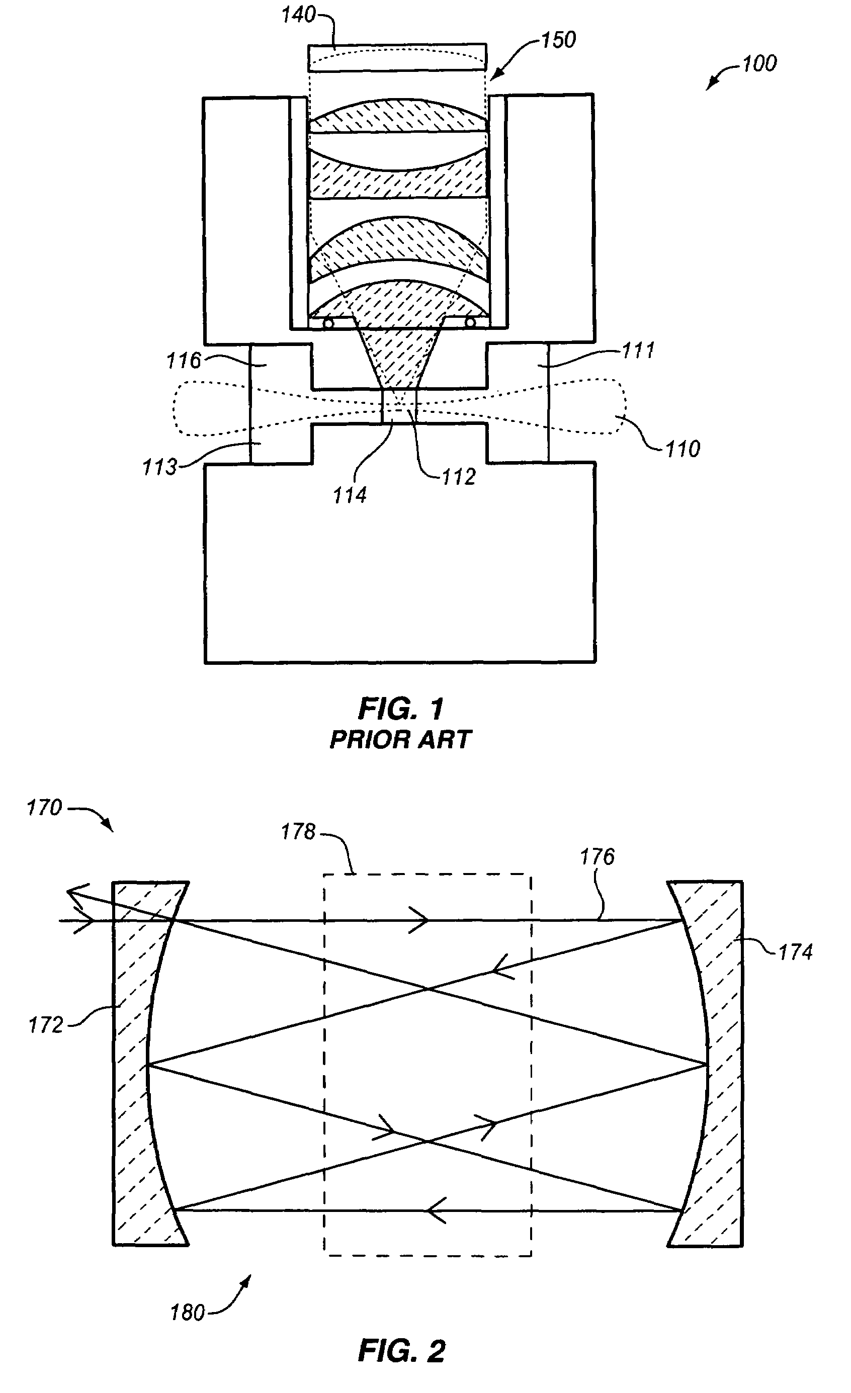
Fundamentally, the geometry of the conventional optical particle counter as shown in FIG. 1 did not allow for the effective use of two-dimensional detector arrays.
Particles in de-ionized water (DIW) and other process fluids can create defects by clinging to wafers, thus interfering with photolithography, as well as physical and chemical vapor deposition processes.
Over the last two years, conventional optical particle counter (OPC) designs have been hard pressed to keep pace with the ITRS DIW sensitivity specifications, and conventional designs have no hope of achieving future targets.
Therefore, there exists no known, practical, liquid OPC design which can provide a significant increase in sensitivity over the conventional design depicted in FIG. 1 using the array described by Knollenberg in U.S. Pat. No. 4,798,465.
Furthermore, this conventional liquid OPC design is unable to keep pace with the International Technology Roadmap for Semiconductor given in Table 1.

Method used


Image

  • Particle counter with improved image sensor array
  • Particle counter with improved image sensor array
  • Particle counter with improved image sensor array

Examples


Embodiment Construction

[0035]In this disclosure, the term “light” is not limited to visible radiation but is used in a broad sense meaning any electromagnetic radiation, including infrared, ultraviolet, extreme ultraviolet, and x-ray radiation. The term “stray light” includes any light that is not wanted, i.e., light that is not light scattered from particles but which can get into the collection optics. Multiple reflected light is a significant source of stray light in prior art particle counters. That is, light that is reflected once, scattered from a scattering source, or diffracted by a lens or aperture can usually be blocked out by other apertures or absorbing black walls even in conventional particle counters because the source of the unwanted light is known. However, multiple reflections make it difficult to determine the direction of the light, and thus often cannot be apertured or otherwise blocked out. As will be discussed below, the invention provides a unique system and method so that stray li...


PUM

PropertyMeasurementUnit
sizeaaaaaaaaaa
areaaaaaaaaaaa
areaaaaaaaaaaa

Abstract

A particle counter for optically detecting an unconstrained particle of less than one micron in size suspended in a flowing liquid includes a sample chamber having a fluid inlet and a fluid outlet; a laser module producing a laser beam; a beam shaping optical system providing a multiple laser beam pattern in the sample chamber, and a CMOS optical detector located to detect light scattered by the particles in the sample chamber. The particle counter has a particle sensing area within the sample chamber in which the intensity of light is at least 10 Watts / mm2, the sensing area having an area of 0.5 square mm or more. The detector has thirty or more detector array elements. In the preferred embodiment, the laser optical system reflects and refocuses the laser beam to effect multiple passes of the same laser beam through the sensing area.

Description

RELATED APPLICATIONS[0001]This application claims priority to U.S. Provisional Application No. 60 / 687,777 filed Jun. 6, 2005.FIELD OF THE INVENTION[0002]The invention in general relates to systems that utilize light scattering principles to detect and count undesirable single particles of less than one micron In size in fluids, which systems are generally referred to in the art as optical particle counters (OPC). More particularly, the invention relates to such a particle counter that utilizes a two-dimensional multi-element detector array.BACKGROUND OF THE INVENTION[0003]Optical particle counters (OPCs) are used to detect and measure the size of individual particles suspended in a fluid. Generally, particle counters are designed to detect particles of less than one micron in size. Each particle that is detected is counted, and an indication of the number of particle counts within a channel, with each channel corresponding to a particular size range, is provided. For particle counte...

Claims


Application Information

Patent Timeline
Patent Type & Authority Patents(United States)
IPC IPC(8): G01N15/02
CPCG01N15/1459G01N15/1434G01N15/1463G01N21/031G01N21/47G01N2015/1062G01N2015/1024G01N15/1433G01N15/0227
Inventor CERNI, TODD A.SEHLER, DWIGHT A.
Owner PARTICLE MEASURING SYST
Learn More