
Method and apparatus for self-calibration and adaptive temperature compensation in GPS receivers

a technology of gps receivers and self-calibration, applied in the field of navigational signal receivers, can solve the problems of increasing search range, increasing frequency drift (increase or decrease) by 5 khz, and temperature-induced frequency drift is therefore uncertain, and achieves accurate estimation, short time-to-first-fix, and fast initialization of the receiver

Inactive Publication Date: 2008-12-02
CSR TECH HLDG
View PDF49 Cites 29 Cited by
  • Summary
  • Abstract
  • Description
  • Claims
  • Application Information

AI Technical Summary

Benefits of technology

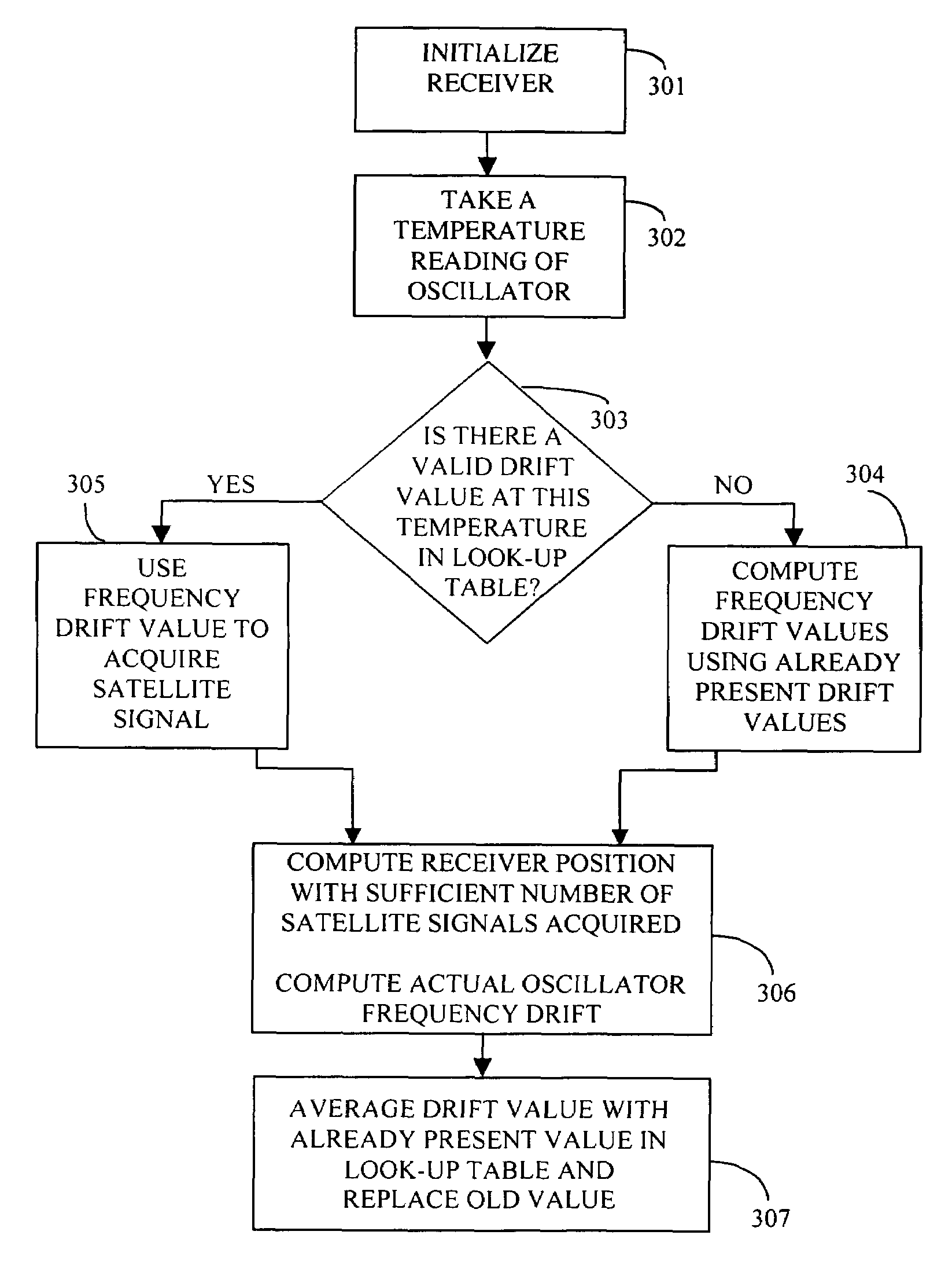
"The present invention provides a new method and apparatus for accurately estimating and compensating for temperature-induced local crystal oscillator frequency drift in a GPS receiver. This invention allows for a fast initialization of the receiver with a relatively short Time-To-First-Fix (TTFF) and does not require any additional cost, factory calibration, or user calibration. The invention uses a non-volatile memory encoding a look-up table that is initialized to all zeros once and is later gradually populated with frequency drift values as the receiver is exposed to different temperatures. The current temperature of the crystal and the associated frequency drift is recorded in the look-up table. The frequency drift values entered into the table are averaged over same temperature readings, thus eliminating any noise present in the use of a single value. The invention is applicable to oscillators that tend to show a reverse frequency drift versus temperature characteristics."

Problems solved by technology

However, due to the velocity of the satellites and the user, this frequency may drift (increase or decrease) by 5 KHz or more.
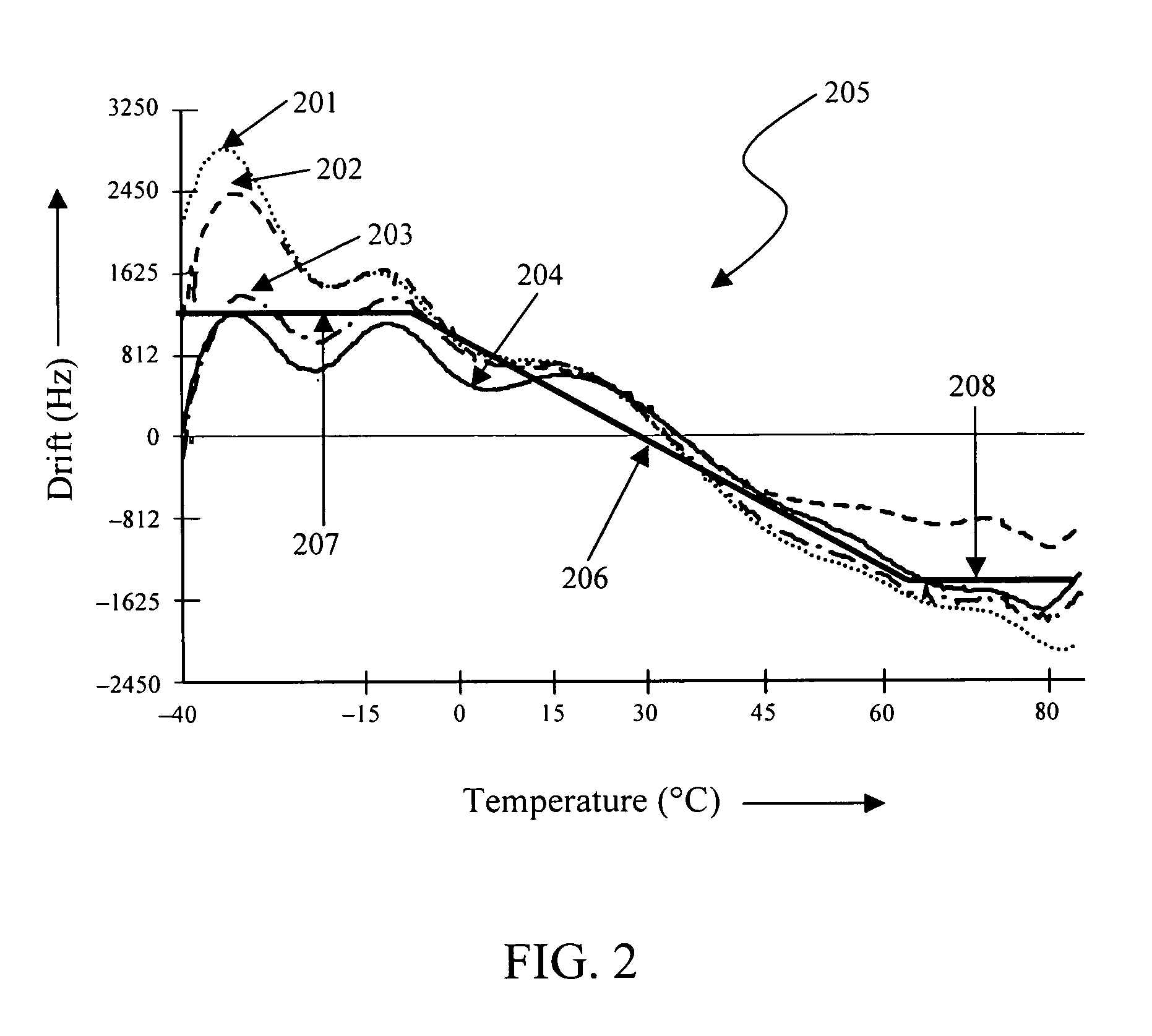
The range of this temperature-induced frequency drift is therefore uncertain and varies from one oscillator to another and increases the search range, especially in the case of high sensitivity GPS receivers, since more frequency components are searched.
As such, most of the existing techniques require factory calibration.
A problem with this approach is that the coefficients are different for each crystal.
Thus, a lot of prior polynomial fitting is needed, which is time-consuming and can be expensive.
Moreover, this approach is not applicable to temperature compensated crystal oscillators (TCXOs).

Method used


Image

  • Method and apparatus for self-calibration and adaptive temperature compensation in GPS receivers
  • Method and apparatus for self-calibration and adaptive temperature compensation in GPS receivers
  • Method and apparatus for self-calibration and adaptive temperature compensation in GPS receivers

Examples


Embodiment Construction

)

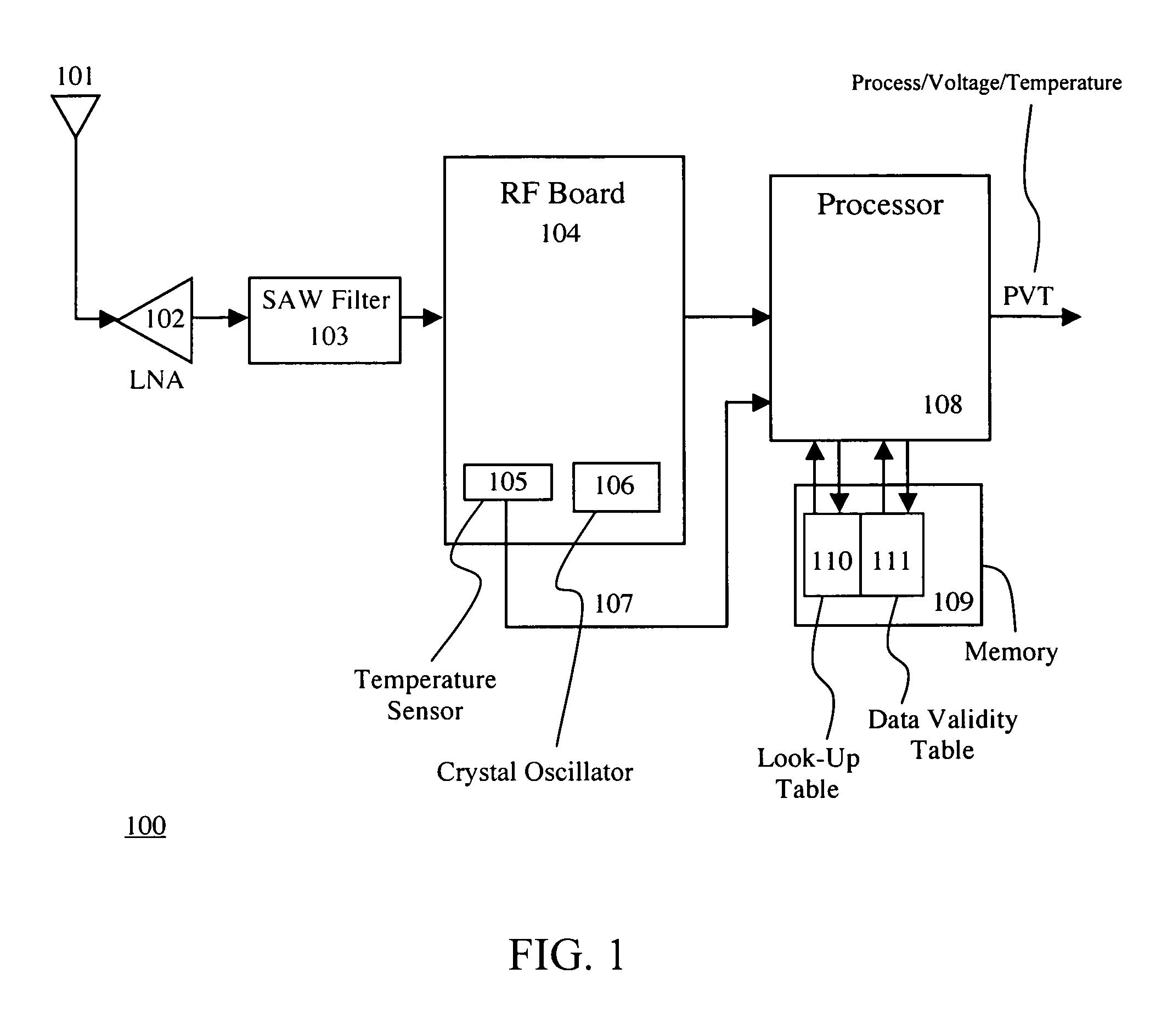
[0027]FIG. 1 illustrates an exemplary GPS receiver 100 implementing an embodiment of the present invention. The receiver 100 comprises a GPS antenna 101 for receiving signals from satellites at a nominal frequency of 1575.42 MHz.

[0028]During an initialization of the GPS receiver, the received signals from the satellites are filtered and amplified so that the signal amplitude and carrier frequency has an acceptable value. In this example, the received signal is amplified by a Low Noise Amplifier (LNA) 102. The antenna 101 may be active, in which case an LNA is integrated therewith. Alternatively, the antenna 101 may be passive, in which case there is no integrated amplifier.

[0029]The signal output from the LNA is filtered using a Surface Acoustic Wave band-pass (SAW) filter 103. The filter 103 removes any noise in the frequency band which is outside of the GPS band.

[0030]The signal then enters the Radio Frequency (RF) section 104, which contains many amplification, signal multiplica...


PUM


Abstract

The invention provides a method and apparatus to optimally estimate and adaptively compensate the temperature-induced frequency drift of a crystal oscillator in a navigational signal receiver. A Read-Write memory encodes two tables, one for looking up frequency drift values versus temperature readings and another one for valid data confirmation on the first table. The initially empty look-up table is gradually populated with frequency drift values while the receiver computes the frequency drift along with its position. During initial start of the receiver or re-acquisition of satellite signals, the stored frequency drift value corresponding to the current temperature is used. If no valid frequency drift value is available, the frequency drift value is computed based on the existing frequency drift values in the table. This invention reduces the Time-To-First-Fix (TTFF) of the receiver and enables the receiver to self-calibrate, thus no additional factory calibration would be necessary.

Description

BACKGROUND OF THE INVENTION[0001]1. Field of the Invention[0002]The present invention relates generally to navigational signal receivers and, more particularly, to an adaptive temperature compensation method and apparatus for estimating and compensating the temperature-induced frequency drifts of a local reference oscillator in a Global Positioning System (GPS) receiver.[0003]2. Description of the Related Art[0004]Satellite-based radio navigation systems have become widely adopted in many commercial and military applications. Exemplary systems in operation or development include the NAVigation Satellite Timing and Ranging Global Positioning System (NAVSTAR GPS), the Global'naya Navigatsionnaya Sputnikovaya Sistema (GLONASS), an European satellite navigation system called GALILEO, the wide area augmentation system (WAAS), and the local area augmentation system (LAAS). These systems permit a user with an appropriate direct sequence spread spectrum (DSSS) signal receiver to determine h...

Claims


Application Information

Patent Timeline
Patent Type & Authority Patents(United States)
IPC IPC(8): H03L1/00G01S1/00G01S19/23
CPCG01S19/235H03L1/026
Inventor WANG, CHI-SHINSHRIDHARA, KUDRETHAYA A.MO, JUNHAN, SHAOWEIWANG, HANSHENG
Owner CSR TECH HLDG
Learn More