Circuit system for a battery electronic control unit

a circuit system and electronic control unit technology, applied in the field of circuit systems, can solve the problems of delay in the propagation of the signal, high cost of the insulator for insulating the propagated signal, and inefficiency of the use of a capacitor for propagating the digital signal having a value represented by binary levels in place of an analog, etc., and achieves the effect of low cost, large device area, and effective application

Inactive Publication Date: 2008-12-30
DENSO CORP
View PDF8 Cites 30 Cited by
  • Summary
  • Abstract
  • Description
  • Claims
  • Application Information

AI Technical Summary

Benefits of technology

[0008]According to a first aspect of the circuit system, a signal output by any specific circuit pertaining to one of a plurality of circuit blocks operating on the basis of power-supply voltages having reference electric potentials different from each other is propagated to another circuit pertaining to another one of the circuit blocks by way of a signal propagation transistor of the specific circuit. A voltage applied to the signal propagation transistor may exceed a power-supply voltage range of a circuit block to which the specific circuit propagating the signal pertains. However, since a voltage-setting means operating for the specific circuit sets a voltage applied to the signal propagation transistor at a level lower than a breakdown voltage of the transistor, the transistor will never be damaged. Thus, electrical insulation is not required in signal propagation beyond a circuit block to which a circuit propagating the signal pertains. As a result, the size and price of the circuit system can be reduced.
[0009]According to a second aspect of the circuit system, an electric potential appearing at the anode of a Zener diode employed in the voltage-setting means operating for a circuit is prescribed by a Zener voltage having an electric potential lower than a voltage range of a circuit block to which the circuit pertains. In addition, an electric potential appearing on a power-supply side of a signal propagation transistor for the circuit is even lower than the electric potential appearing at the anode by a difference in electric potential between the control and output terminals of a voltage-setting transistor employed in the voltage-setting means. Thus, a voltage applied to the signal propagation transistor can be much reduced, being set at a level lower than the breakdown voltage of the transistor.
[0015]Thus, in an attempt made to use a circuit pertaining to any circuit block as a circuit for managing signals input to and output from each specific cell block as signals for controlling the charging and discharging processes of the specific cell block, naturally, a difference in voltage between the signals becomes a problem. By applying this circuit system, however, the signals can be propagated without insulating the signals and a configuration allowing the charging and discharging processes to be managed in a concentrated manner can be implemented at a low cost.
[0016]According to an eighth aspect of the circuit system, the secondary battery power supply functions as a motor-driving power supply for providing power to a motor for driving an electric-powered vehicle into a travel motion and the circuit system is applied to an ECU for controlling the motor-driving power supply. That is, the motor-driving power supply for providing power to a motor for driving an electric-powered vehicle into a travel motion comprises a number of secondary battery cells connected to each other in series and the terminal voltage of numerous battery cells is approximately in the range 100 V to 400 V. Thus, since the charging and discharging processes of a number of cell blocks need to be managed in a concentrated manner, the circuit system can be applied very effectively to the ECU.
[0017]According to a ninth aspect of the circuit system, the circuit system is created as an integrated circuit on a semiconductor substrate. That is, if a device such as a photo coupler is used as a means for insulating a propagated signal, a physical space of such a device is required in a portion for propagating the signal as a light beam. If a controller employing such a device for insulating a propagated signal is assumed to be a controller created as a semiconductor integrated circuit, a large area of the device is required, raising a problem of a big chip size and high cost of the controller. In accordance with the present circuit system, on the other hand, since a signal can be propagated between cell blocks without adoption of an insulating structure, the circuit system can be implemented as an integrated circuit having an extremely small size.

Problems solved by technology

In addition, the use of a capacitor for propagation of a digital signal having a value represented by binary levels in place of an analog is not efficient.
However, this solution has a problem that an insulator for insulating a propagated signal is expensive and a photo-electrical conversion process carried out by the photo coupler introduces a delay in the propagation of the signal.

Method used


Image

  • Circuit system for a battery electronic control unit
  • Circuit system for a battery electronic control unit
  • Circuit system for a battery electronic control unit

Examples


first embodiment

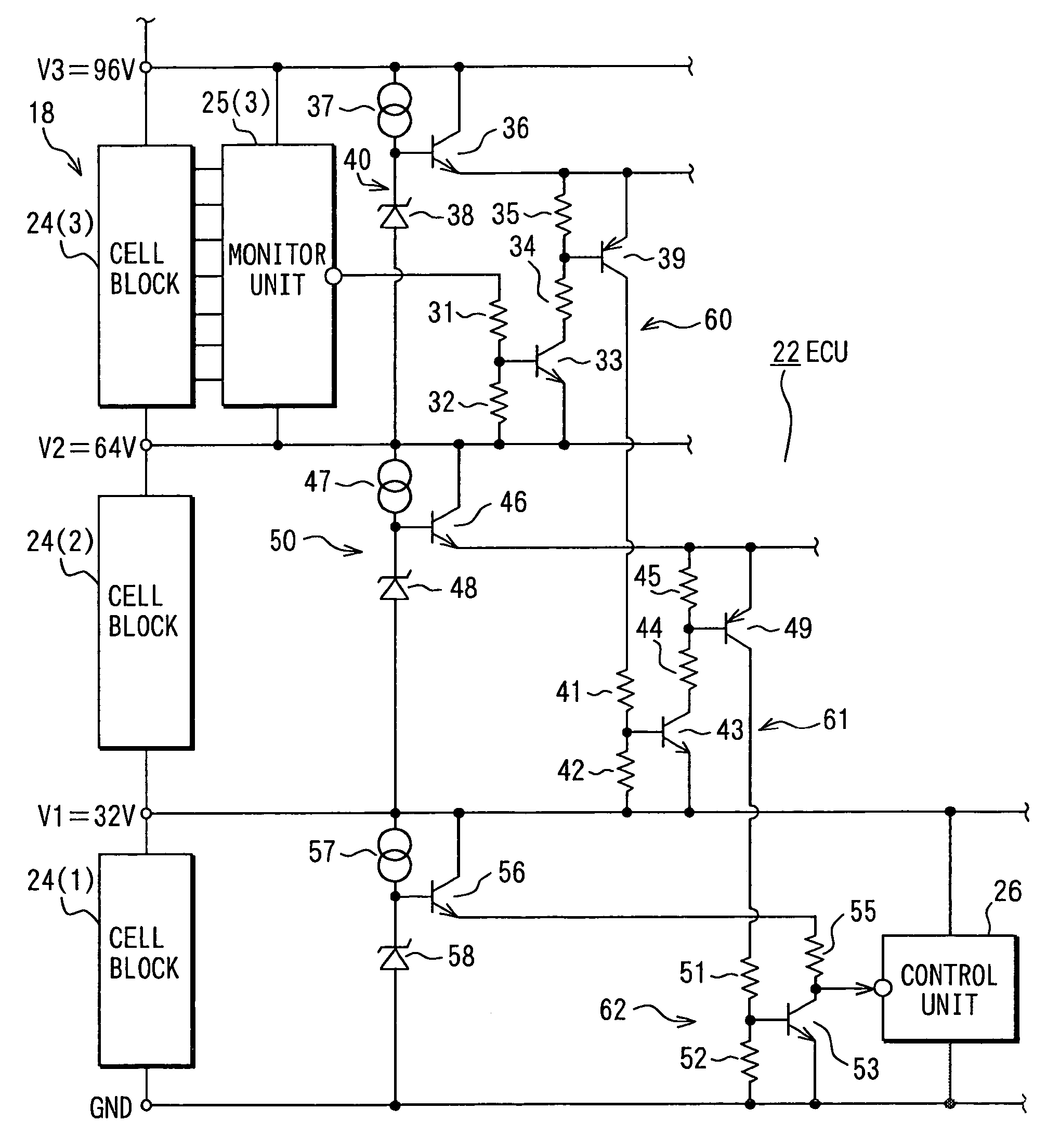
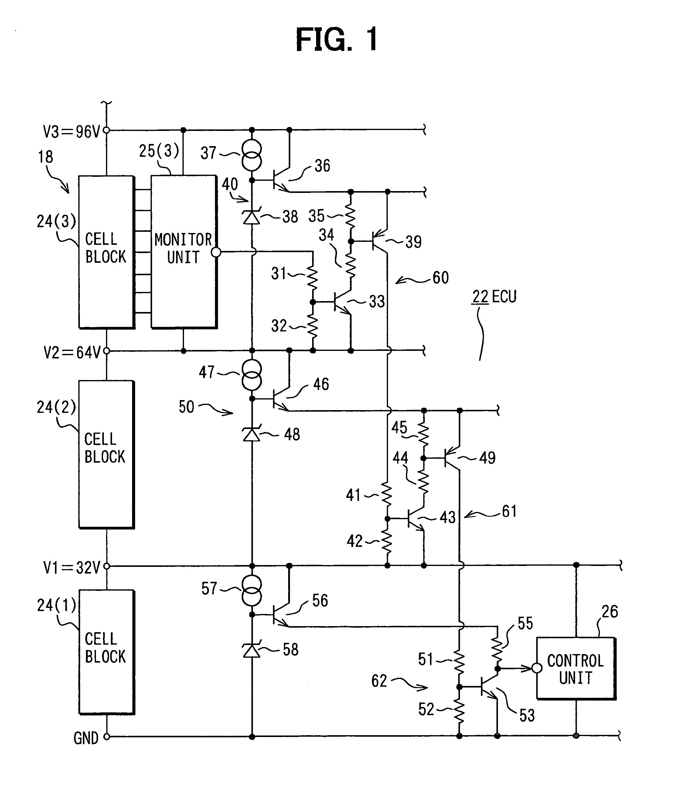
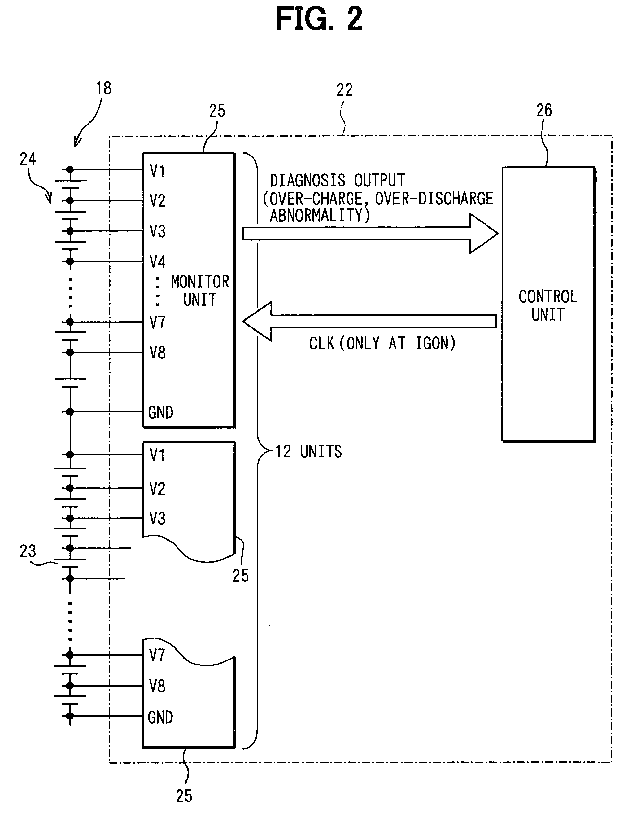
[0025]A first embodiment is explained by referring to FIGS. 1 to 3 for a case in which a circuit system is applied to a battery ECU for controlling a primary battery of a hybrid electric-powered vehicle. FIG. 3 is a diagram roughly showing the system configuration of a hybrid electric-powered vehicle (HEV) 11. In the HEV 11, a power division mechanism 13 divides a driving force generated by the engine (ENG) 12 into forces applied to motor / generators (MGs) 14 and 15. The MG 14 works mainly as a generator and adjusts the apportion of power through the power division mechanism 13. That is, the MG 14 executes the function of a transmission in addition to the function of a generator. An inverter 16 adjusts the output load of the MG 14. On the other hand, the MG 15 drives running wheels 17 of the HEV 11. The MG 15 has a configuration to drive the running wheels 17 in collaboration with the engine 12 in dependence on a control condition.

[0026]A main battery 18 supplies a voltage in the ran...

second embodiment

[0051]FIG. 4 is a diagram showing a second embodiment. In this figure, circuit elements identical with their respective counterparts employed in the first embodiment are denoted by the same reference numerals as the counterparts and their descriptions are not repeated in order to avoid duplications. Only differences between the first and second embodiments are explained. The second embodiment implements a circuit configuration in which the control unit 26 on the low-voltage side outputs a signal to the cell-block monitor unit 25(3) on the high-voltage side. The figure shows only a portion of the battery ECU 22.

[0052]An output terminal of the control unit 26 is connected to the ground through a series circuit comprised of resistors 65 and 66. The junction point between the resistors 65 and 66 is connected to the base of an NPN transistor 67, which serves as a signal propagation transistor. The emitter of the transistor 67 is connected to the ground. On the other hand, the collector o...


PUM


Abstract

A battery ECU controls a main battery composed of a plurality of battery cells connected to each other in series. The battery cells are grouped into cell blocks each having a cell-block monitor circuit. A control unit controls charging / discharging processes on the basis of signals output by the cell-block monitor circuit. A signal output by a cell-block monitor circuit on a high-voltage side turns on a transistor for propagating a signal to a cell-block monitor circuit on a middle-voltage side. In the cell-block monitor circuit on a middle-voltage side, the propagated signal turns on another transistor for further propagating a signal to a cell-block monitor circuit on a low-voltage side. In the cell-block monitor circuit on a low-voltage side, the propagated signal turns on a further transistor for outputting a signal to a control unit.

Description

CROSS REFERENCE TO RELATED APPLICATION[0001]This application is based upon, claims the benefit of priority of, and incorporates by reference the contents of, Japanese Patent Application No. 2004-62149 filed on Mar. 5, 2004.FIELD OF THE INVENTION[0002]The present invention relates to a circuit system comprising a plurality of circuit blocks, each of which includes a circuit operating on the basis of a power-supply voltage in one of a plurality of voltage sub-ranges obtained from dividing the voltage range of a predetermined power supply.BACKGROUND OF THE INVENTION[0003]A battery employed in an electric-powered vehicle is required to generate a high voltage for driving a travel-motion motor. Normally, the battery includes a plurality of secondary batteries connected to each other in series. FIG. 6 is a diagram showing such a configuration as disclosed in JP-A-11-248,755, the contents of which are incorporated herein by reference. Voltage detection terminals T1, T3 and T5 of voltage ge...

Claims


Application Information

Patent Timeline
Patent Type & Authority Patents(United States)
IPC IPC(8): H02J7/00H02J7/14H01L27/04B60L50/15B60R16/02H01L21/822H03K17/10
CPCH02J7/0026H02J7/0029H01L27/1203H01L29/7317Y02T10/7055H02J7/0016Y02T10/70
Inventor SOBUE, SATOSHIYAMAMOTO, TOMOHISA
Owner DENSO CORP
Why Eureka
Try Eureka