
Pipelined data relocation and improved chip architectures

a data relocation and chip technology, applied in the field of semiconductor nonvolatile data storage system architectures, can solve the problems of high constant performance penalty of data transfer and verification, high probability of the need to rewrite the entire block with a high penalty in performance and time-out/latency, and the eeprom architecture does not allow independent access to data, etc., to achieve high error rate memory, accelerate complex data operations, and improve the effect of memory

Active Publication Date: 2009-02-10
SANDISK TECH LLC
View PDF59 Cites 62 Cited by
  • Summary
  • Abstract
  • Description
  • Claims
  • Application Information

AI Technical Summary

Benefits of technology

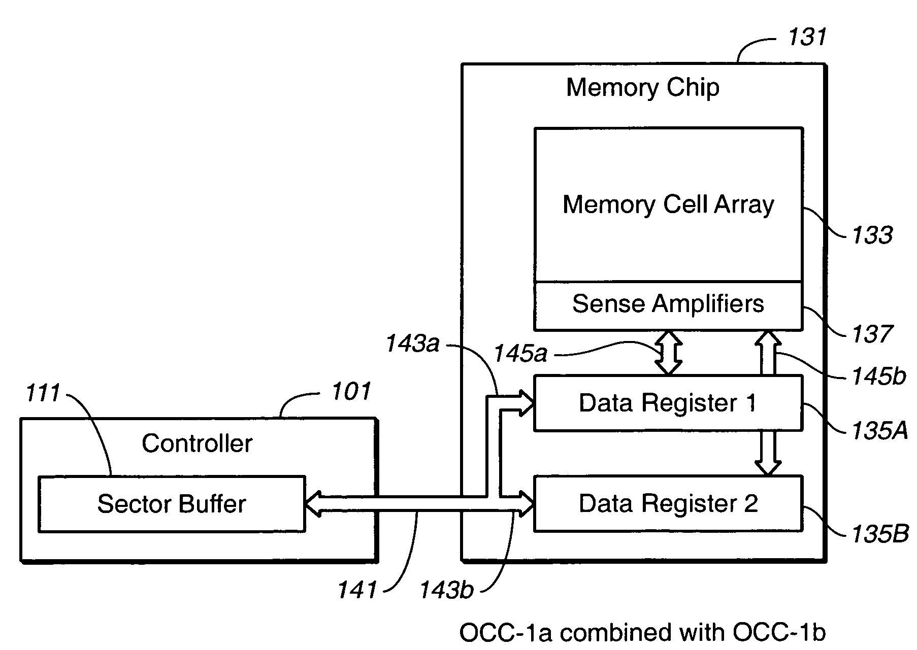
[0029]According to one principal aspect of the present invention, briefly and generally, a data relocation method is presented which allows the correction of data errors during garbage collection operations without any penalty to overall performance and time-out / latency in defect tolerant systems, thereby allowing the usage of flash memory with higher error rate in performance critical applications. In a more general aspect of the present invention, improved memory architectures allows data transfers between controller and the memory concurrently with read and program operations, thus accelerating complex data operations such as data relocation, or garbage collection, and write-read back-verify processes, particularly for systems with high error rate memories.
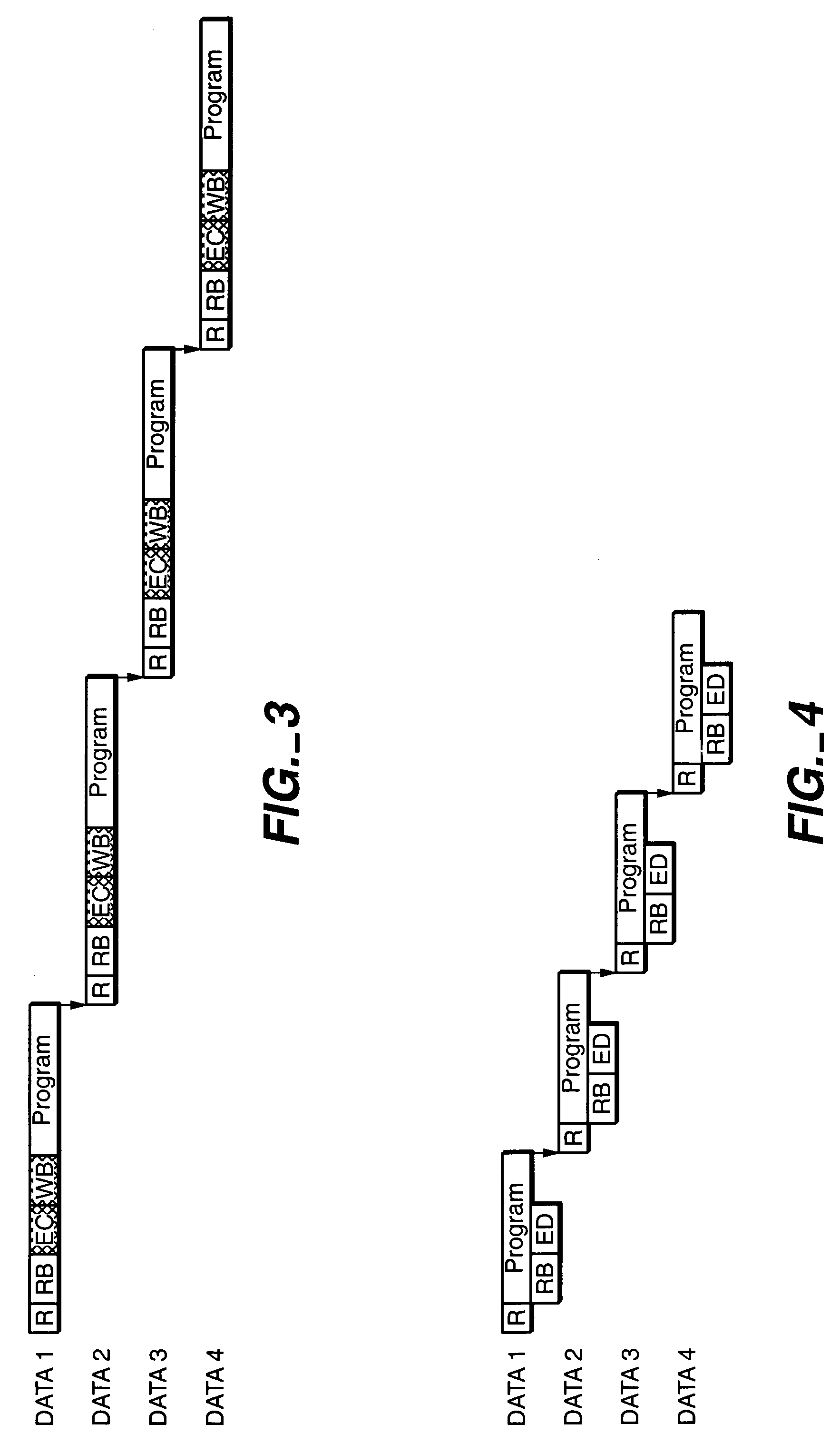
[0030]The invention describes a method of pipelined relocation of multiple data portions, where an integrity check and error correction of a current data portion is done concurrently with the programming of the previous data portion. When multiple pages (or data portions) are being relocated from one memory location to another (inside a chip or from one chip to another) the system always reads one data page in advance. After the advance page read, the system starts programming the previously read page. While the previously read page is being programmed, the system checks the data integrity of the advance read page and corrects the error if necessary and transfers it back to the flash memory register. Additionally, the system can also use the “wait” during the transfer of one data set for correction of the other data set. Thus, as the data check and correction happens simultaneously with the previous page programming there is no time penalty in the case of system with high error rate unless the error correction takes longer than a page programming operation. In this way, the data relocation pipelining hides error correction operations and the systems no longer has additional performance penalty when there is a read error. The system then can use a memory with much higher error rate without compromising the performance.
[0033]In another alternate embodiment, the memory again has two data registers, but only one can be directly accessed by the controller, while only the other can directly exchange data with the memory array. By incorporating a swap operation where the contents of the two registers can be exchanged, the alternated embodiment can function in a manner largely equivalent the embodiment with two independent registers. The features of the various architectures can be combines for further improvements in performance.

Problems solved by technology

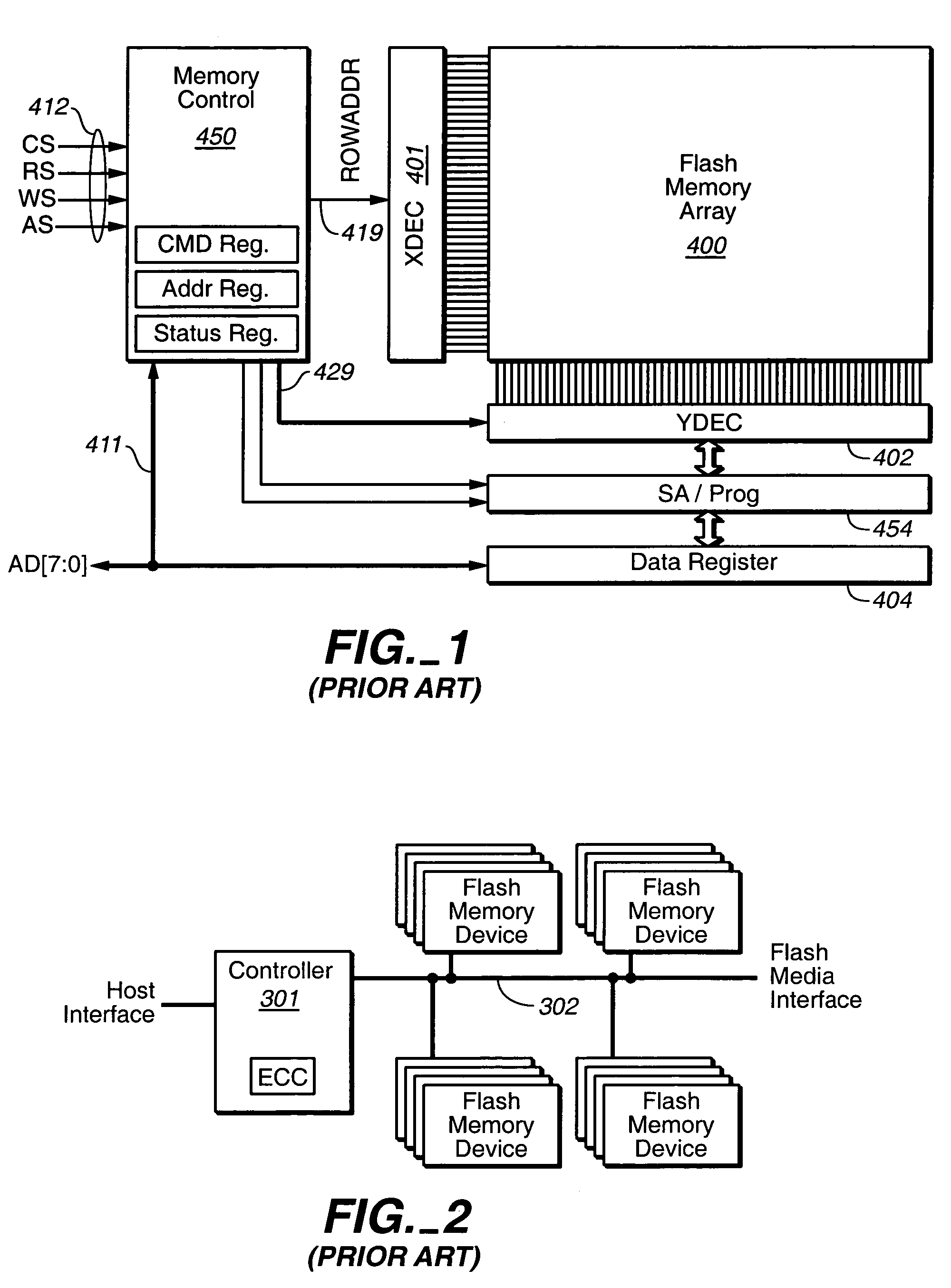
Prior art methods describe the data relocation operation as a consecutive data read, then data integrity check and error correction, if necessary, before writing the data to a new location, so that there is a high constant performance penalty of data transfer and verification.
The integrity check is done concurrently with the data write so that, in the case of error, there is a high probability of the need to rewrite the entire block with a high penalty in performance and time-out / latency.
Prior art system flash / EEPROM architectures do not allow independent access to the data in one on-chip buffer to while another buffer is used for concurrent read or program operation.
Thus, operations that include mixture of reads and writes, like garbage collection, cannot be pipelined in prior art systems.

Method used


Image

  • Pipelined data relocation and improved chip architectures
  • Pipelined data relocation and improved chip architectures
  • Pipelined data relocation and improved chip architectures

Examples


Embodiment Construction

[0054]In a first aspect, the present invention describes a data relocation method that allows correction of data errors during garbage collection operations without any penalty to overall performance and time-out / latency in defect tolerant systems, and thus, allows usage of flash memory with higher error rate in performance critical applications. Other aspects are improved flash chip architectures that allows data transfers between controller and flash chip concurrently with read and program operations, thus accelerating complex data operations, like data relocation (garbage collection) and Write-Read Back-Verify, typical for systems with high error rate memory.

[0055]The various aspects of the present invention are applicable to non-volatile memory systems in general. Although the description below, as well as that in the Background, is given mainly in terms of an EEPROM Flash memory embodiment, the particular type of storage unit used in the memory array is not particularly importa...


PUM


Abstract

The present invention present methods and architectures for the pipelining of read operation with write operations. In particular, methods are presented for pipelining data relocation operations that allow for the checking and correction of data in the controller prior to its being re-written, but diminish or eliminate the additional time penalty this would normally incur. A number of architectural improvements are described to facilitate these methods, including: introducing two registers on the memory where each is independently accessible by the controller; allowing a first memory register to be written from while a second register is written to; introducing two registers on the memory where the contents of the registers can be swapped.

Description

BACKGROUND OF THE INVENTION[0001]This invention pertains to the field of semiconductor non-volatile data storage system architectures and their methods of operation, and has application to data storage systems based on flash electrically erasable and programmable read-only memories (EEPROMs) and other types of memory system.[0002]A common application of flash EEPROM devices is as a mass data storage subsystem for electronic devices. Such subsystems are commonly implemented as either removable memory cards that can be inserted into multiple host systems or as non-removable embedded storage within the host system. In both implementations, the subsystem includes one or more flash devices and often a subsystem controller.[0003]Flash EEPROM devices are composed of one or more arrays of transistor cells, each cell capable of non-volatile storage of one or more bits of data. Thus flash memory does not require power to retain the data programmed therein. Once programmed however, a cell must...

Claims


Application Information

Patent Timeline
Patent Type & Authority Patents(United States)
IPC IPC(8): G06F3/00G11C29/00G11C7/10G11C16/34
CPCG11C7/1039G11C7/1051G11C16/3436G06F11/1008G06F12/0246G06F9/38G11C7/10G11C16/34G11C29/00
Inventor GOROBETS, SERGEY ANATOLIEVICHCONLEY, KEVIN M.
Owner SANDISK TECH LLC
Learn More