Measuring instrument and concentration measuring device

Active Publication Date: 2009-02-17
ARKRAY INC
View PDF19 Cites 38 Cited by
  • Summary
  • Abstract
  • Description
  • Claims
  • Application Information

AI Technical Summary

Benefits of technology

[0011]It is therefore an object of the present invention to provide a concentration measurement utilizing a concentration measuring device and a measurement instrument, having an advantage in production cost, reducing a burden of user, and capable of performing more exact concentration measurement. First, when the concentration measurement is performed with the concentration measuring devi

Problems solved by technology

However, when the user determines the calibration curve by the button operation, the operation is a burden to the user.
Further, he or she may forget to perform the operation.
Similarly, the use of the correction chip is a burden to the user, and he or she may forget to determine the calibration curve.
If the user forgets the determination of the calibration curve, the measurement of blood sugar level cannot be performed appropriately.
Particularly, the correction chip increases the production cost since it requires ad

Method used


Image

  • Measuring instrument and concentration measuring device
  • Measuring instrument and concentration measuring device
  • Measuring instrument and concentration measuring device

Examples


first embodiment

[0072]FIGS. 1-9 show the present invention.

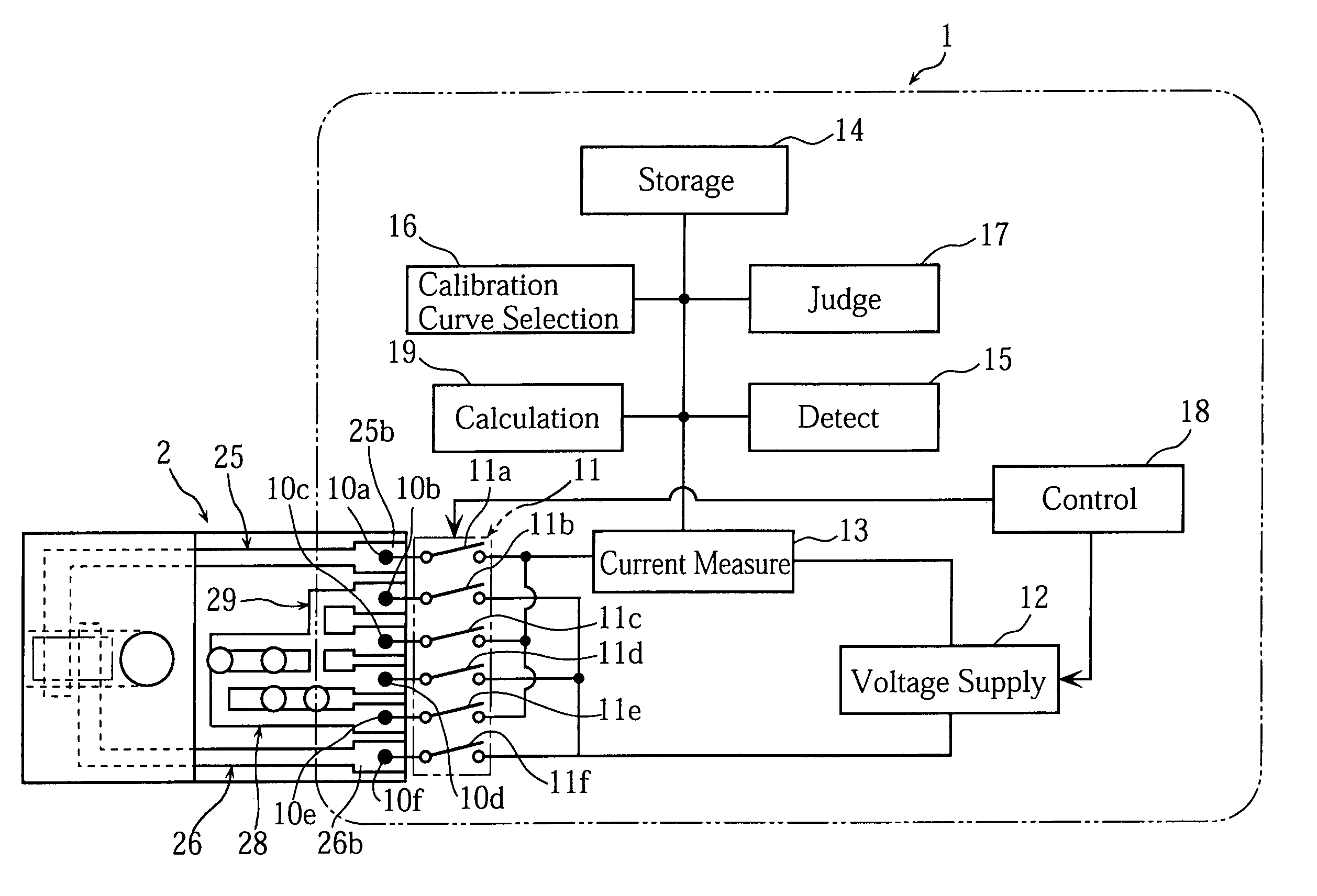
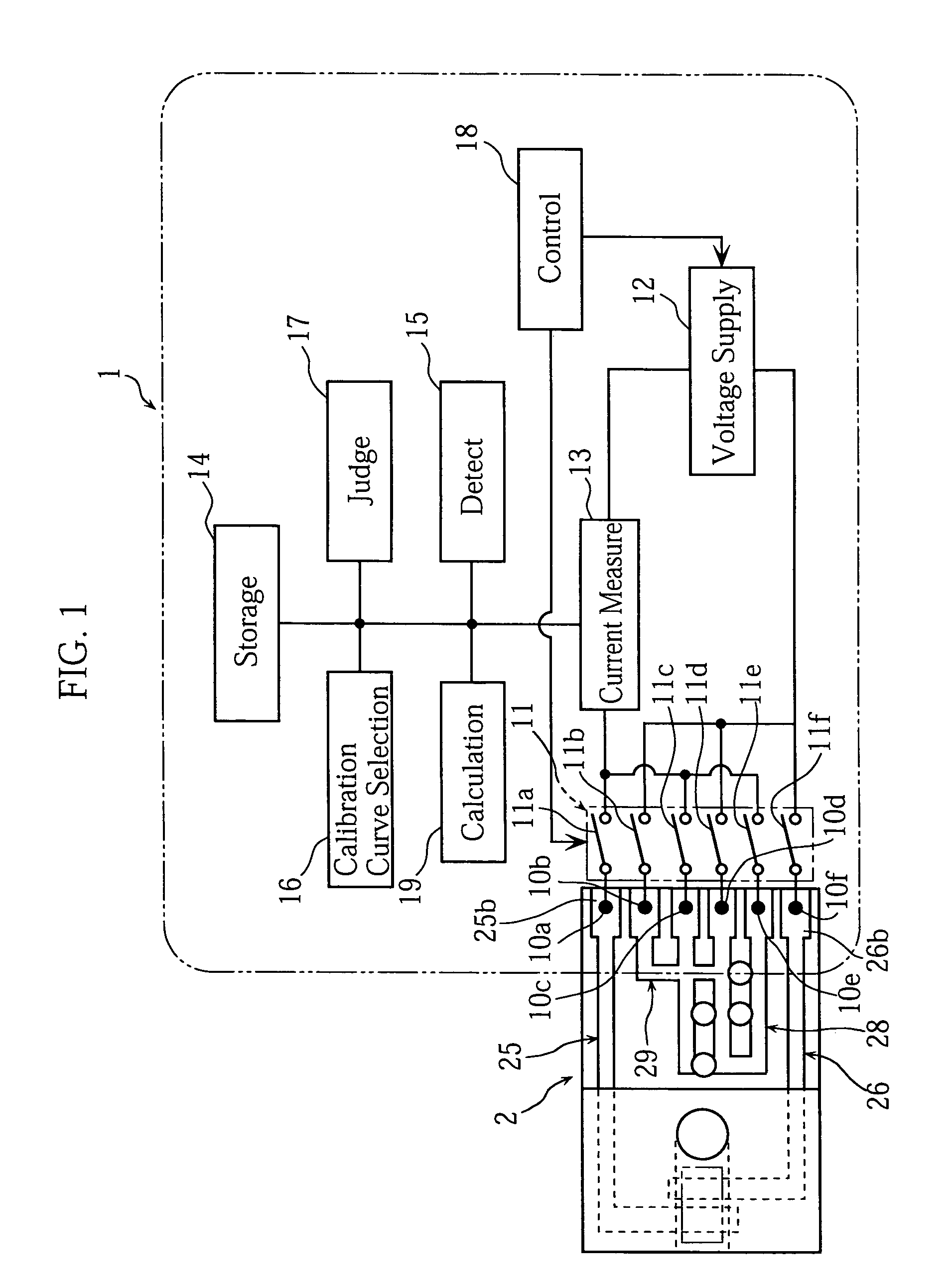
[0073]As shown in FIG. 1, a concentration measuring device 1 with a biosensor 2 mounted thereto is used for calculating the concentration of a specific component in a sample liquid. The concentration measuring device 1 includes first-sixth terminals 10a-10f, a switch unit 11, a voltage applying unit 12, an electric current measuring unit 13, a storage unit 14, a detection unit 15, a calibration curve selection unit 16, a judging unit 17, a control unit 18 and a calculating unit 19.

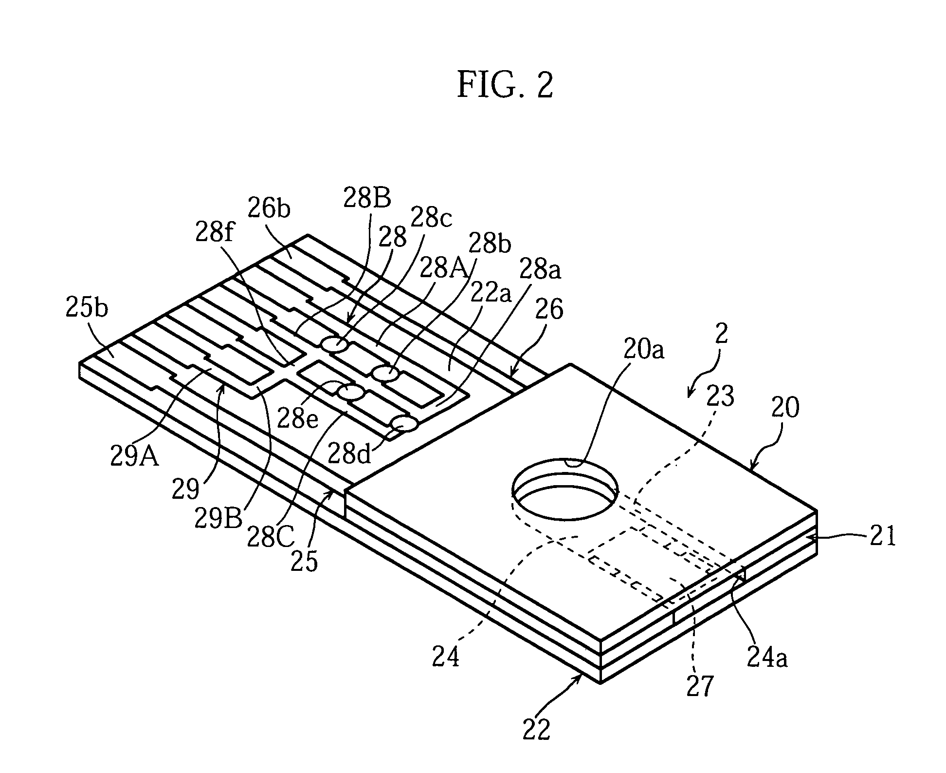
[0074]As shown in FIGS. 2 and 3, the biosensor 2 includes a cover 20, a spacer 21 and a substrate 22, these members forming a channel 24.

[0075]The channel 24 communicates with outside via a hole 20a formed in the cover 20 and an opening 23a of a slit 23 formed in the spacer 21. The opening 23a serves as a sample liquid inlet 24a. The sample liquid fed via the inlet 24a flows through the channel 24 toward the hole 20a by capillary action.

[0076]The substrate 22, mad...

sixth embodiment

[0136]FIGS. 17A and 17B show the present invention.

[0137]A biosensor 3H has an attribute information output section 30H including first and second individual information output sections 30Ha, 30Hb. The first individual information output section 30Ha is formed in the same portion as the attribute information output section 30G of the biosensor 3H shown in FIG. 15. The first individual information output section 30Ha is formed in a strip extending over substantially the entire width of the substrate 22. The second individual information output section 30Hb is formed between the ends 25b, 26b of the working and counterpart electrodes 25, 26. The second individual information output section 30Hb is shorter than the first individual information output section 30Ha. The first and second individual information output sections 30Ha, 30Hb are fabricated in the same production step and made of the same material, and therefore differ in resistance.

[0138]The concentration measuring device incl...

seventh embodiment

[0140]FIGS. 18A-18D show the present invention.

[0141]A biosensor 3I has an attribute information output section 30I including first-third individual information output sections 30Ia-30Ic. The first-third individual information output sections 30Ia-30Ic are formed in the same region as the attribute information output section 30G. The first-third individual information output sections 30Ia-30Ic are formed in a strip extending widthwise of the substrate 22. The first-fourth terminals 45a-45d contact the first-third individual information output sections 30Ia-30Ic in attaching the biosensor 3I to the concentration measuring device.

[0142]This arrangement can output various kinds of information with the use of the first-third individual information output sections 30Ia-30Ic.

[0143]If the substrate 22 has a length L of 10 mm and a width W of 5 mm for example, it is difficult to set a dimension D between the ends 25b, 26b of the electrodes 25, 26 and the shorter end 22b of the substrate 22 ...


PUM

PropertyMeasurementUnit
Electrical resistanceaaaaaaaaaa

Abstract

The measurement instrument includes an attribute information output section to output attribute information about the attributes of the measurement instrument as an electric physical value. The attribute information is based on at least one of the conditions including a resistance of the attribute information output section, a location of the attribute information output section, and the size of a region on which the attribute information output section is formed. The attribute information may be used to select the calibration curve suitable for the measurement instrument. The attribute information may be one that relates to a specific measurement standard applied to the measurement instrument.

Description

[0001]This application is a 371 of PCT / JP02 / 10137, filed on Sep. 27, 2002, which claims foreign priority from Japanese application 2001-301009, filed on Sep. 28, 2001, and Japanese application 2002-78183, filed on Mar. 20, 2002.TECHNICAL FIELD[0002]The present invention relates to a measurement instrument such as a biosensor, a method of making the measurement instrument, a set of the measurement instrument and a measurement auxiliary instrument, a sensor cartridge for accommodating a plurality of the measurement instruments, and a concentration measuring device for calculating the concentration of a specific component in a sample liquid with the measurement instrument.BACKGROUND ART[0003]In measuring a specific component in body fluid (e.g. glucose in blood), redox reaction is utilized in general. A handy-size blood measuring device is generally used for the easy measurement of blood sugar at or away from home. In use, a disposal biosensor for providing an enzyme reaction field is ...

Claims


Application Information

Patent Timeline
IPC IPC(8): G01N27/327G01N27/447G01N33/487
CPCG01N33/48771G01N35/00693G01N35/00732G01N2035/00089
Inventor SAKATA, TETSUYAKASAI, TOKUOKOBAYASHI, TAIZO
Owner ARKRAY INC
Why Eureka
Try Eureka