Self diagonostic flame ignitor

a flame ignitor and self-diagnosis technology, applied in the field of ignitor, can solve the problems of pulverized coal flame stability decline, ignitor wire supplying energy to an ignitor spark element may burn up, oil-fired ignitors are still subject to this problem, etc., and achieve the effect of reliable spark action

Inactive Publication Date: 2009-02-17
GENERAL ELECTRIC TECH GMBH
View PDF23 Cites 9 Cited by
  • Summary
  • Abstract
  • Description
  • Claims
  • Application Information

AI Technical Summary

Benefits of technology

[0012]It is an object of the present invention to provide an oil-fired ignitor having reliable spark action in a high temperature environment.
[0014]Another object of the present invention is to provide an ignitor having higher reliability than conventional ignitors.

Problems solved by technology

Failure of an ignitor can result in unsafe accumulations of unburned main fuel and air, resulting in massive explosive damage.
However, when the load goes down and the coal supply is thereby decreased, the stability of the pulverized coal flame is also decreased, and it is therefore common practice to use the ignitors or warm-up guns to maintain flame in the combustion chamber, thus avoiding the accumulation of unburned coal dust in the combustion chamber and the associated danger of explosion.
In some conventional ignitors, there is a risk that an ignitor wire supplying energy to an ignitor spark element may burn up due to the high temperatures, especially when insufficient cooling air is supplied to the ignitor.
However, oil-fired ignitors are still subject to this problem.
The spray produced by conventional atomizers used in oil-fired ignitors frequently has too many large droplets, resulting in insufficient oxygen at the base of the flame.
An insufficient amount of oxygen results in excessive smoke formation, resulting in an unacceptable opacity from the stack.
Lack of a flame could be due to any one of a faulty ignitor fuel supply, a faulty ignitor compressed air, or a faulty ignitor spark source.
Further, a flame could actually be present, and the flame detector itself could be sending a false lack of flame signal.
Currently, there is no way for service personnel to know what ignitor component has failed without physically examining that ignitor.
Performing this routine maintenance is both costly and time consuming.

Method used


Image

  • Self diagonostic flame ignitor
  • Self diagonostic flame ignitor
  • Self diagonostic flame ignitor

Examples


Embodiment Construction

)

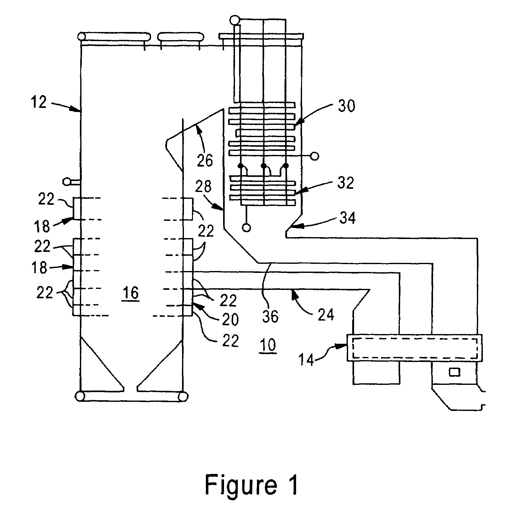
[0034]Referring now to the drawings, and more particularly to FIG. 1, there is depicted a conventional fossil fuel-fired power generation system, generally designated by the reference numeral 10, having installed therein a preferred embodiment of the ignitor of the present invention. It should be understood that the ignitor of the present invention could be utilized in industrial or utility installations other than that depicted in FIG. 1. The fossil fuel-fired power generation system 10 includes a fossil fuel-fired steam generator 12 and an air preheater 14.

[0035]The fossil fuel-fired steam generator 12 includes a burner region. It is within the burner region 16 of the fossil fuel-fired steam generator 12 that the combustion of fossil fuel and air, in a manner well-known to those skilled in this art, is initiated. To this end, the fossil fuel-fired steam generator 12 is provided with a conventional firing system 18.

[0036]The firing system 18 includes a housing, preferably in the f...


PUM


Abstract

Techniques for monitoring operation of a flame ignitor are provided. In one embodiment, multiple inputs are received. The inputs are received from at least one of a first group of inputs and a second group of inputs. The first group includes a flame rod voltage, a stop signal for deactivation of the flame ignitor, a fuel supply interruption signal, and an air supply interruption signal. The second group includes a start signal for activation of the flame ignitor, and a flame proven signal indicating presence of a flame produced by the flame ignitor. If inputs from the first group are received, a cause of a failure of the flame ignitor is determined. If inputs from the second group are received, a reliability of the flame ignitor is determined.

Description

FIELD OF THE INVENTION[0001]The present invention relates to an ignitor for a fossil fuel fired combustion chamber, and more particularly to an ignitor having improved performance and reliability.BACKGROUND OF THE INVENTION[0002]In order to begin the combustion process inside a fossil fuel fired combustion chamber, such as that found in industrial and utility boilers, there must be an energy source to begin the self-sustaining combustion reaction of main fuel and air inside the combustion chamber. Current practice is to use a light fuel oil, natural gas, or propane ignitor of a size between input of 0.5 to 20 Million Btu / hr for each of several fuel admission compartments of the combustion chamber.[0003]Ignitors have a dedicated fuel and air supply and an energy source, typically a spark plug, to produce a flame. In operation, fuel and air are introduced to the ignitor and a spark provides the energy to begin a self-sustaining reaction that keeps the ignitor burning. Proof that the i...

Claims


Application Information

Patent Timeline
Patent Type & Authority Patents(United States)
IPC IPC(8): G08B17/12
CPCF23N5/123F23N5/242F23N2023/04F23N2023/08F23N2023/38F23N2023/54F23N2027/26F23N2027/30F23N2029/02F23N2029/12F23N2031/08F23N2039/02F23N2039/06F23D2900/00014F23N2223/04F23N2223/08F23N2223/38F23N2223/54F23N2227/26F23N2227/30F23N2229/02F23N2229/12F23N2231/08F23N2239/02F23N2239/06
Inventor MATTESON, DAVID J.SEQUIN, MICHEL J.TOBIASZ, REBECCA L.SUTTON, JAMES P.
Owner GENERAL ELECTRIC TECH GMBH
Why Eureka
Try Eureka