
Bi-directional PLC transceiver device

a transceiver device and planar light technology, applied in the direction of instruments, optics, optical light guides, etc., can solve the problems of increasing the size and cost of the apparatus, poor wavelength isolation, manufacturing difficulties, etc., and achieve the effect of low cross-talk of light and high wavelength isolation

Inactive Publication Date: 2009-02-17
PAULA ROBINS AS CALLATERAL AGENT
View PDF50 Cites 20 Cited by
  • Summary
  • Abstract
  • Description
  • Claims
  • Application Information

AI Technical Summary

Benefits of technology

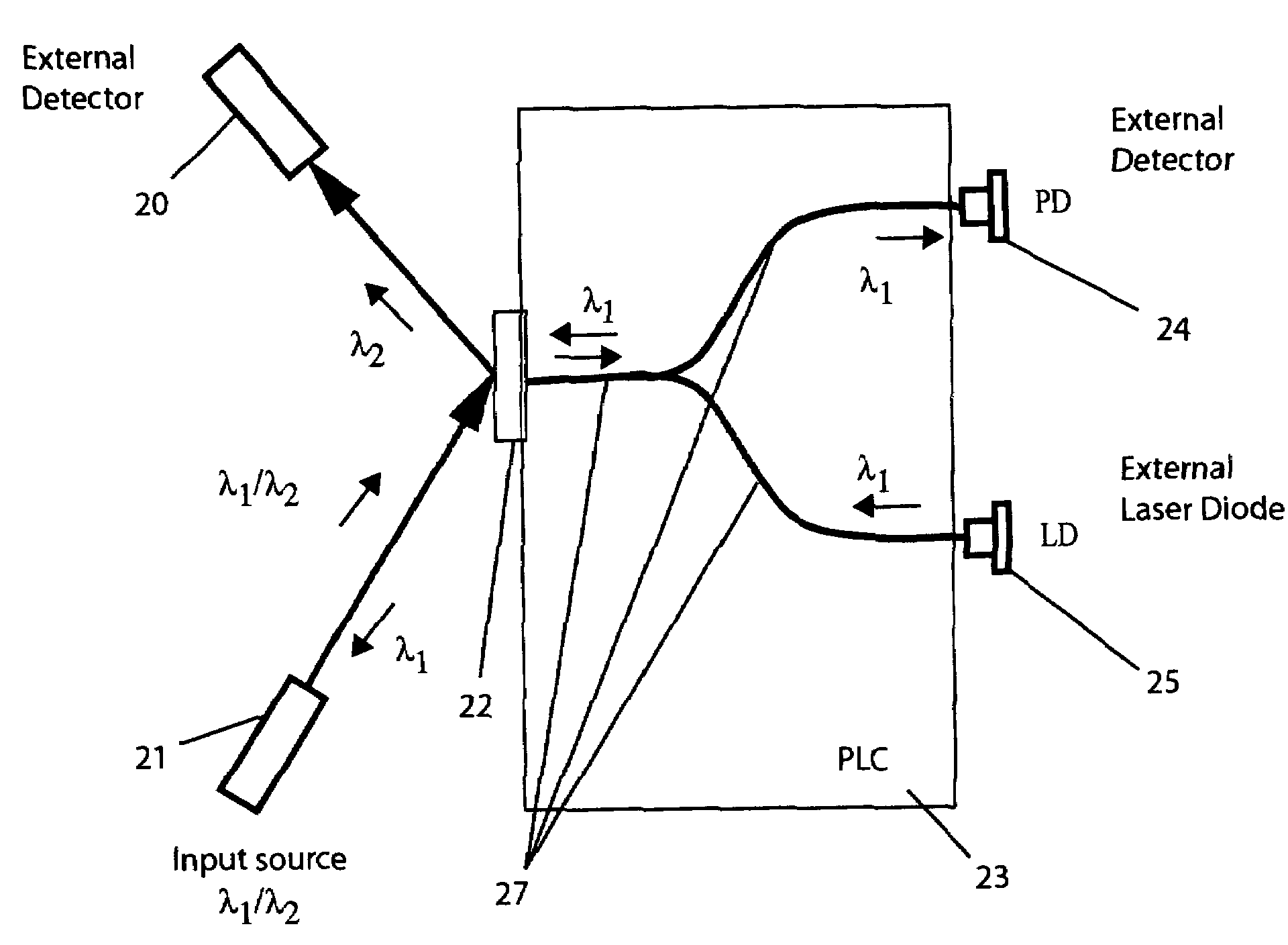
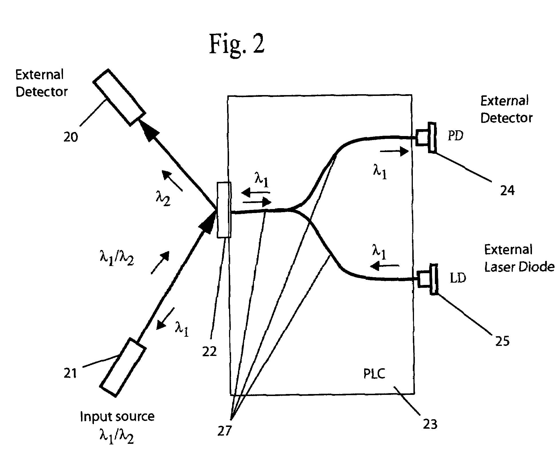
[0009]The invention comprises an improved bi-directional optical transceiver device for multiple wavelength signals that has a high level of wavelength isolation at the receivers of the device and low cross-talk of light between an external laser transmitter and the receivers. The device uses a combination of high spatial light confinement waveguide structures and a variable thickness dielectric wavelength selective filter (WSF) in a WDM planar light wave circuit (PLC) assembly.
[0010]Cross-talk in the device is minimized by using a specific waveguide design and wavelength isolation is enhanced by one or more dielectric interference filters placed on the surface of the PLC. In addition, the PLC can be produced using a material that absorbs light selectively so that the material itself acts as a WSF.
[0012]By placing one or more WSF's on the surface of the PLC, a waveguide channel trench for each filter is not required, and thicker filters can be used to reduce chip manufacturing costs. In addition, a dichroic or interference WSF can be advantageously placed on an edge of the PLC chip using a direct deposition process with a signal detector placed directly over the WSF.

Problems solved by technology

A major problem with conventional bulk optic transceiver devices is scattering of light from the edges and surfaces of the various components, lenses, WDM filters, and beam splitters, leading to cross-talk, i.e. light from the external 1300 nm emitter leaking into the photodetector receivers, and poor wavelength isolation due to insufficient blockage of selective light by the dielectric filters.
A major manufacturing problem with prior art PLC based transceiver apparatus is the required filter thickness tolerance, on the order of micrometers, necessary for positioning the dielectric filter in a slot created directly in the optical path of the waveguides of the device.
As such, the handling of thin filters creates manufacturing difficulties.
In addition, the fabrication of a waveguide channel trench designed to receive the filter requires a relatively large surface area chip, increasing the size and cost of the apparatus.

Method used


Image

  • Bi-directional PLC transceiver device
  • Bi-directional PLC transceiver device
  • Bi-directional PLC transceiver device

Examples


Embodiment Construction

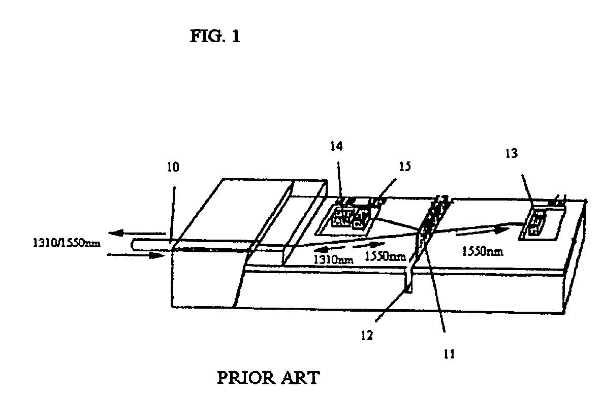
[0022]A typical prior art data and video transmission transceiver apparatus is illustrated in FIG. 1, where bi-directional wavelength optical communication signals can be sent and received simultaneously. In such apparatus, an optical fiber 10 transmitting upstream and downstream 1310 nm and 1550 nm signals is interfaced to the bi-directional transceiver device where a wavelength division multiplexer (WDM) filter assembly 11, placed in a slot 12, separates the incoming 1310 nm and 1550 nm signals and distributes them between a 1550 nm photodiode detector 13 and a 1310 nm photodiode detector 14. Simultaneously, a 1310 nm laser diode 15 interfaced to the bi-directional transceiver device transmits 1310 nm signals upstream into the fiber. Clear separation of signals in the apparatus is a problem because of cross-talk between the 1310 nm signal from the built-in laser diode leaking into the 1310 nm and 1550 nm photodetectors, and because of poor wavelength isolation at each of the 1310 ...


PUM


Abstract

An integrated bi-directional transceiver device for multiple wavelength optical signals that has a high level of wavelength isolation at the receivers of the device and low cross-talk of light between an external laser transmitter and the receivers. A WDM planar light wave circuit (PLC) assembly combines high spatial light confinement waveguide structures and a variable thickness dielectric wavelength selective filter (WSF) on the surface of the device to reflect a first wavelength signal and to pass a second wavelength signal. Embodiments of the invention include branching waveguide structures and folded path waveguide assemblies with multiple WSF's.

Description

FIELD OF THE INVENTION[0001]This invention relates to bi-directional planar light circuit (PLC) transceiver devices that enable analog and digital media communication over a single fiber.BACKGROUND OF THE INVENTION[0002]Optical transceiver devices are well known in the art and are often found in applications where a bi-directional data stream is employed for the transmission of both video, in one direction, and data, in two directions, over a single mode fiber optic cable. A 1300 nm emitter and a 1300 nm receiver are generally used for data communication and a 1550 nm receiver for video information.[0003]Typically, these devices have been produced using conventional bulk optical elements such as lenses, WDM filters, and beam splitters, built into the device, to separate the analog and digital transmission wavelengths and to direct the signals back and forth from the emitter and receivers to the input optical fiber carrying the transmission signal. Recently, a new generation of devic...

Claims


Application Information

Patent Timeline
IPC IPC(8): G02B6/26G02B6/42
CPCG02B6/12004G02B6/30G02B6/4246
Inventor TYAN, RONGCHUNGKANG, HEE CHOONMENDOZA, EDGAR A.KEMPEN, LOTHAR U.
Owner PAULA ROBINS AS CALLATERAL AGENT
Learn More