Data communication system, method and apparatus for communicating a data signal formed of successive data elements

a data signal and data communication technology, applied in the field of data communication, can solve the problems of unsuitable ethernet frame timing for transmitting a 2.8224 mhz dsd sample clock, and none of the known systems provide an interconnection suitable for linking dsd audio devices, etc., to achieve the effect of easy design and implementation, large bandwidth, and proven electromagnetic compatibility

Inactive Publication Date: 2009-03-03
SONY UK LTD
View PDF5 Cites 55 Cited by
  • Summary
  • Abstract
  • Description
  • Claims
  • Application Information

AI Technical Summary

Benefits of technology

[0018]The present invention use the physical layer of a link (e.g. an Ethernet link) to provide a data communication system for transmission of clocked digital data such as DSD data. Note that the present invention is also applicable to bit stream audio data other than DSD data such as one-bit, delta-sigma modulated audio data at a variety of sample rates or floating point data formats. The advantages of using the physical layer of Ethernet for such data transmission are that it offers a large bandwidth, has proven electromagnetic compatibility and has error detection functionality (cyclic redundancy checks) already in place. Use of the physical layer makes the logic easy to design and implement. There is no need to be concerned with hardware addressing and implementation of windowing protocols as would likely be required if the audio data were encoded using higher layer (e.g. MAC layer) technology. Furthermore at the physical layer level, Ethernet data transmission is robust and spectrum controlled so that electromagnetic emissions are low. The invention provides an elegantly simple and convenient way of synchronising the two ends of such a link which is applicable to the transmission of one-bit or multi-bit data.

Problems solved by technology

It is a problem to provide interconnections between large-scale multi-track production equipment for DSD audio such as multi-channel ADC / DACs, DSD mixers and multi-channel DSD recorders both because of the high audio bandwidth required for the audio data interconnection and because of the difficulty of transmitting the high frequency (64 Fs) audio sample clock between devices without compromising the integrity of the signal e.g. due to electromagnetic interference from the audio data signal.
However, none of these known systems provides an interconnection suitable for linking DSD audio devices.
This is because Ethernet frame timing is completely unsuitable for transmitting a 2.8224 MHz DSD sample clock.

Method used


Image

  • Data communication system, method and apparatus for communicating a data signal formed of successive data elements
  • Data communication system, method and apparatus for communicating a data signal formed of successive data elements
  • Data communication system, method and apparatus for communicating a data signal formed of successive data elements

Examples


Embodiment Construction

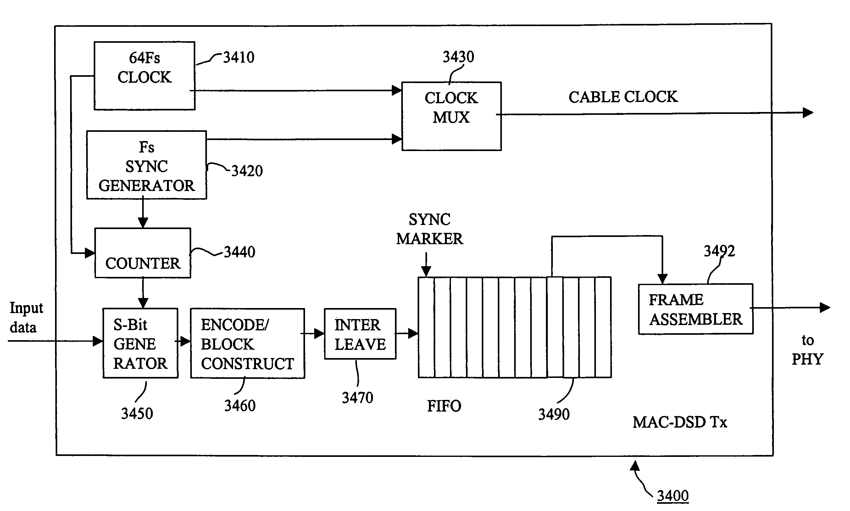
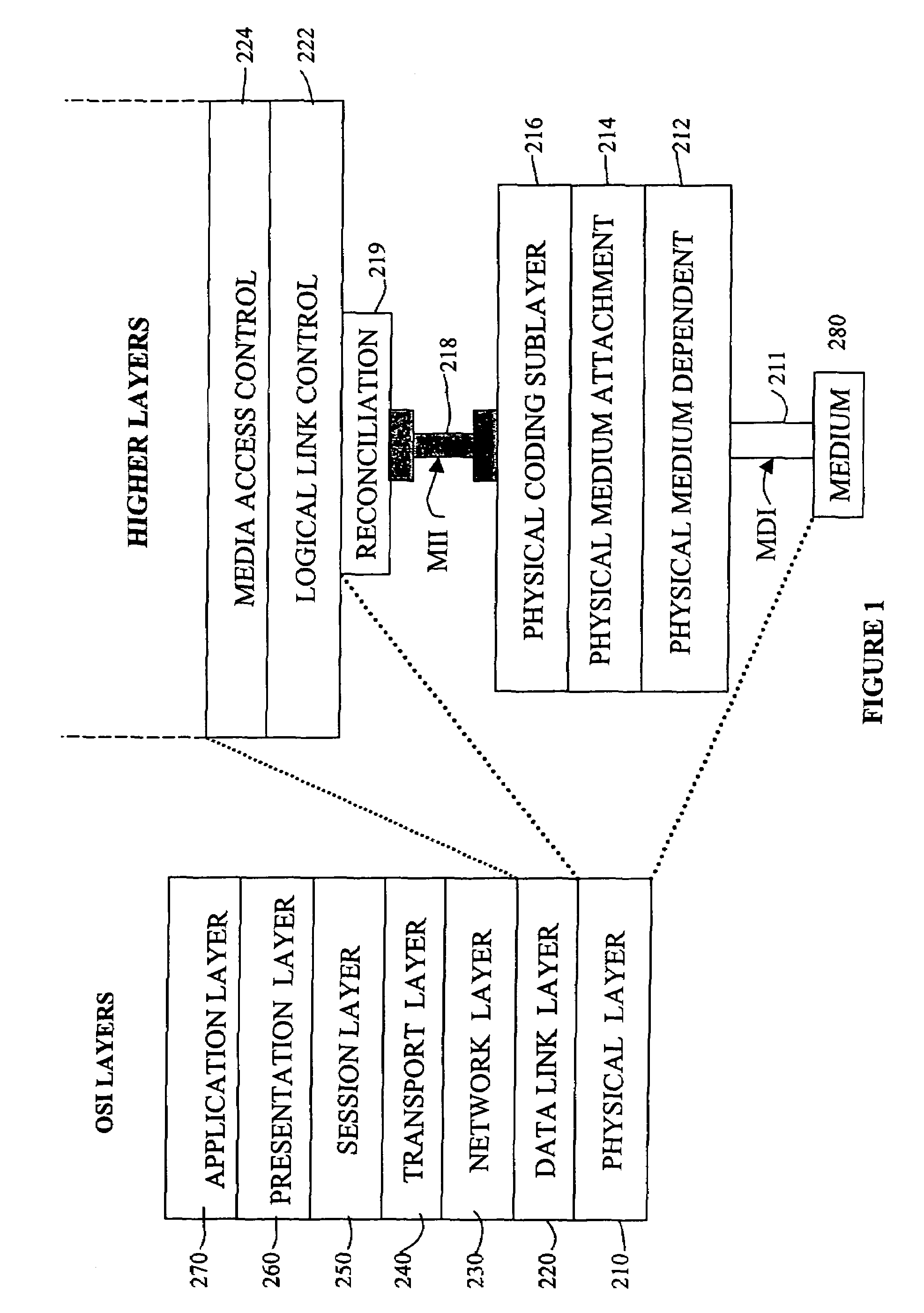
[0104]As described above, some known audio networking systems use the data link layer of Ethernet for transmission of uncompressed digital audio data at standard sampling frequencies of around 48 kHz. By way of contrast, embodiments of the present invention use the physical layer of Fast Ethernet to provide a point to point connection for transmission of high frequency (2.8224 MHz) digital audio data. The advantages of using the physical layer of Fast Ethernet for audio data transmission are that it offers a large bandwidth, has proven electromagnetic compatibility and has error detection functionality (cyclic redundancy checks) already in place. Use of the physical layer makes the logic easy to design and implement. There is no need to be concerned with hardware addressing and implementation of windowing protocols as would likely be required if the audio data were encoded using higher layer (e.g. MAC layer) technology. Furthermore at the physical layer level, Ethernet data transmis...


PUM


Abstract

A data communications system for communicating a data signal formed of successive data elements, said system comprising a transmission node; a reception node; and a link providing a data connection from said transmission node to said reception node; in which: said transmission node comprises a clock signal transmitter for transmitting a synchronisation clocking signal to said reception node via said link, said synchronisation clocking signal having synchronising features occurring at a frequency lower than a data element rate; an assembler for assembling elements of said data signal into data frames, each data frame having a plurality of successive data elements of said data signal, for transmission to said reception node via said link, said assembler being responsive to said synchronisation clocking signal so as to set a synchronisation flag associated with a data element having a first predetermined temporal relationship with a synchronising feature of said synchronisation clocking signal; and said reception node comprises: a detector detecting a synchronising feature of said synchronisation clocking signal received from said transmission node; a disassembler for disassembling received data frames to regenerate said data signal, said disassembler being operable to detect a data element associated with a set synchronisation flag; an output unit for outputting a data element associated with a set synchronisation flag at a second predetermined temporal relationship with respect to said synchronising feature of said received synchronisation clocking signal; said first and second predetermined temporal relationships being arranged so that a predetermined system latency exists between input of a data element to said transmission node and subsequent output of that data element by said reception node.

Description

BACKGROUND OF THE INVENTION[0001]1. Field of the Invention[0002]This invention relates to data communication.[0003]An example of a problem in data communication will be described in the context of communicating so-called Direct Stream Digital audio data. However, the present invention is applicable to other types of clocked data, such as multi-bit audio data or video data.[0004]2. Description of the Prior Art[0005]Direct Stream Digital (DSD) is a high-resolution single-bit audio coding system used for the so-called Super Audio CD consumer disc format. DSD was developed with a view to producing audio signals comparable to those reproduced from the best analogue formats. DSD signals can produce a frequency response from DC to 100 kHz and have a dynamic range of greater than 120 dB across the audio band.[0006]DSD makes use of 1-bit digital audio. 1-bit oversampling converters exploit a law of information theory whereby sample width can be traded off against sampling rate to effect conv...

Claims


Application Information

Patent Timeline
Patent Type & Authority Patents(United States)
IPC IPC(8): H04L27/00H03K9/00H04L29/06H04J3/00H04J3/06H04L7/00
CPCH04J3/00H04L7/0008
Inventor PAGE, MICHAEL
Owner SONY UK LTD
Why Eureka
Try Eureka