
Monolithic silicon-based phased arrays for communications and radars

a phased array and silicon-based technology, applied in the field of wireless communications, can solve the problems of system waste, increased interference, and increased effects of multi-path fading and interferen

Active Publication Date: 2009-03-10
CALIFORNIA INST OF TECH
View PDF18 Cites 21 Cited by
  • Summary
  • Abstract
  • Description
  • Claims
  • Application Information

AI Technical Summary

Benefits of technology

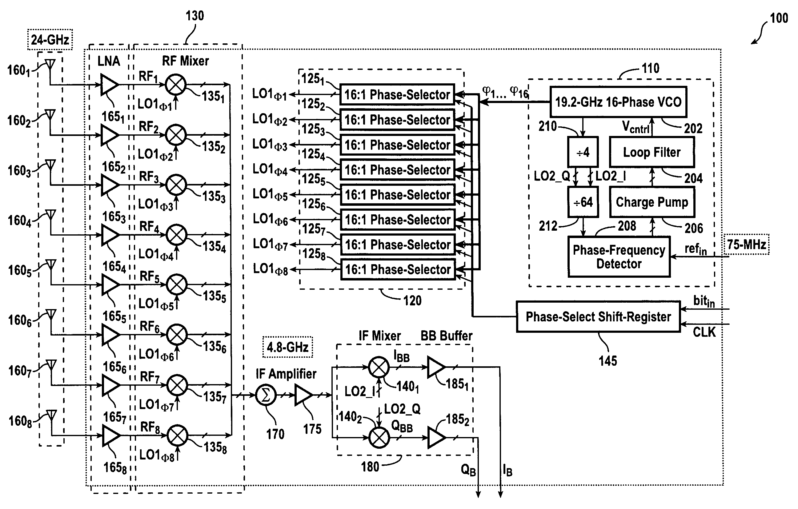
The present invention is about a phased-array receiver that includes N RF mixers and a signal summing block. Each RF mixer receives a pair of input signals, one from a receive antenna and one from a local oscillator (LO) phase signal. The LO phase signal is selected from among M phases of the LO using a phase selector associated with each RF mixer. The RF mixers generate output signals that are summed by the signal summing block. The summed signals are then applied to IF mixers that also receive the I / Q signals of a divided-down replica of the LO signal. The phased-array receiver is operative at high RF frequencies and can achieve phase-shifting with high resolution. The invention provides a more efficient and accurate way to receive RF signals and downconvert them to the baseband.

Problems solved by technology

Such systems, however, have a number of drawbacks.
For example, the transmitter in such systems radiates electromagnetic power in all directions, only a small fraction of which reaches the intended receiver; this results in a considerable amount of waste in the transmitted power.
Furthermore, because the electromagnetic propagation is carried out in all directions, the effects of phenomenon such as multi-path fading and interference are more pronounced.
However, a single-directional antenna is typically not well adapted for portable devices whose orientation may require fast and frequent changes via mechanical means.
However, conventional phased-arrays require a relatively large number of microwave modules, adding to their cost and complexity.
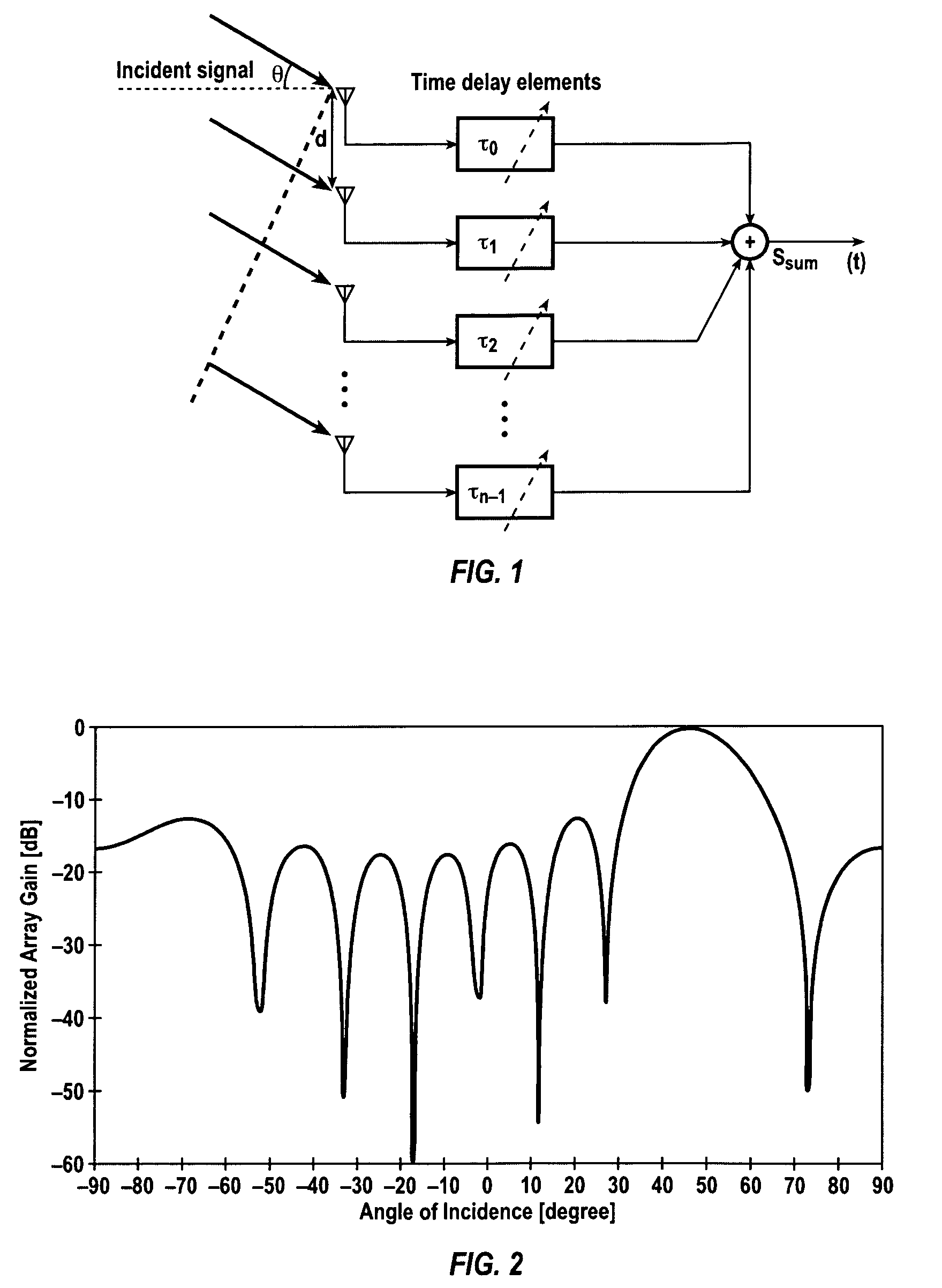
However, adjustable time delays at RF are challenging to integrate due to such non-ideal effects as, e.g., loss, noise, and nonlinearity.

Method used


Image

  • Monolithic silicon-based phased arrays for communications and radars
  • Monolithic silicon-based phased arrays for communications and radars
  • Monolithic silicon-based phased arrays for communications and radars

Examples


Embodiment Construction

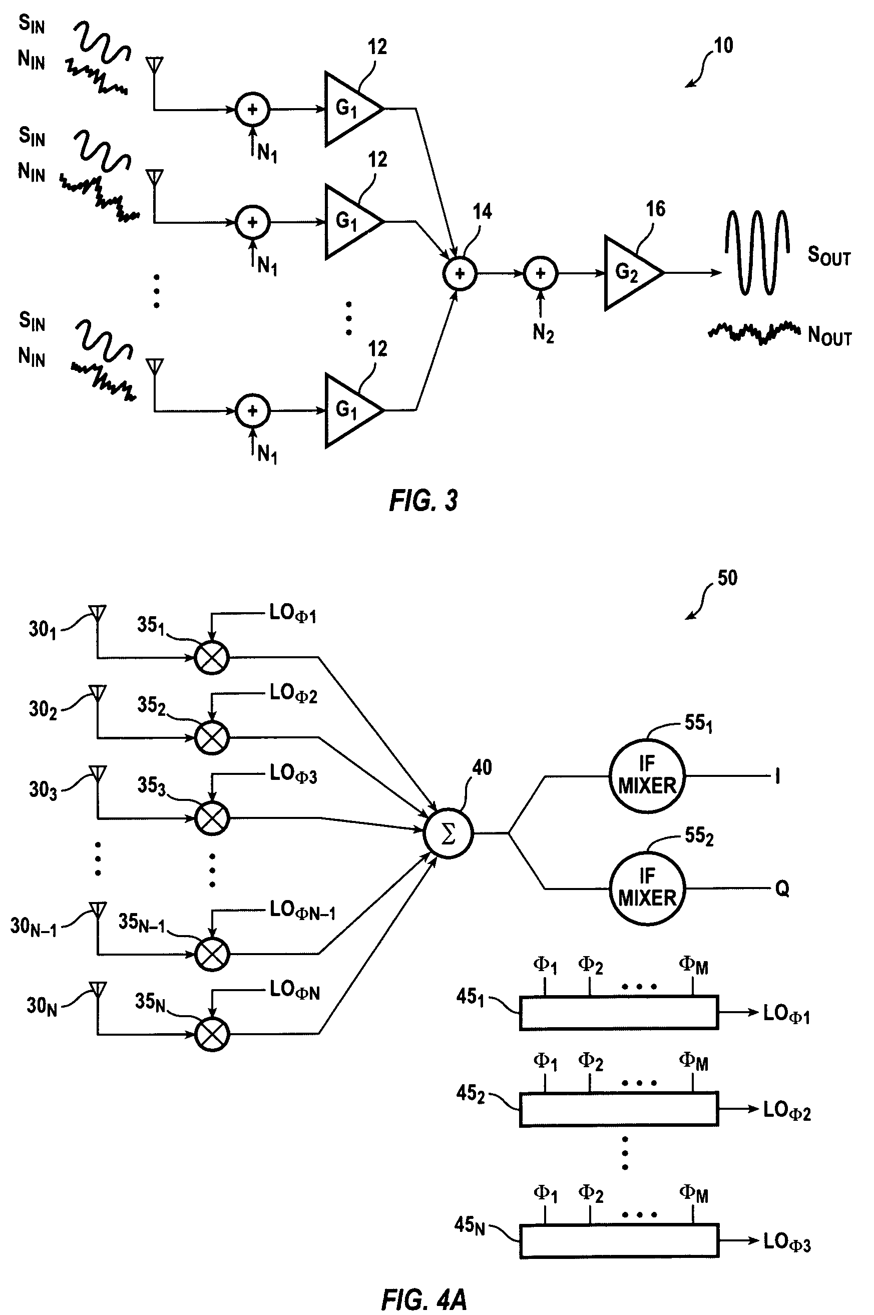
[0055]In accordance with one embodiment of the present invention, an N-element phased-array receiver, such as phased-array receiver 50 shown in FIG. 4A, includes, in part, N RF mixers 351, 352, 353 . . . 35N-1, 35N, and a signal summing block 40. Each RF mixer 35i, where i is an integer ranging from 1 to N, is adapted to receive a pair of input signals. The first signal applied to each RF mixer 35i is an RF signal received by a receive antenna 30i associated with that RF mixer 35i. Accordingly, there are N receive antennas 30i each associated with a different one of the N RF mixers 35i. The second signal applied to each RF mixer 35 is a phase signal LOφi selected from among M phases φ1, φ2 . . . φM of a local oscillator. Each of N phase selectors 451, 452, 453 . . . 45N-1, 45N—each phase selector being associated with a different one of the N RF mixers 35i—receives the M different phases φ1, φ2, . . . φM of the local oscillator independently and, in response to one or more control s...


PUM


Abstract

A phased-array receiver is adapted so as to be fully integrated and fabricated on a single silicon substrate. The phased-array receiver is operative to receive a 24 GHz signal and may be adapted to include 8-elements formed in a SiGe BiCMOS technology. The phased-array receiver utilizes a heterodyne topology, and the signal combining is performed at an IF of 4.8 GHz. The phase-shifting with 4 bits of resolution is realized at the LO port of the first down-conversion mixer. A ring LC VCO generates 16 different phases of the LO. An integrated 19.2 GHz frequency synthesizer locks the VCO frequency to a 75 MHz external reference. Each signal path achieves a gain of 43 dB, a noise figure of 7.4 dB, and an IIP3 of −11 dBm. The 8-path array achieves an array gain of 61 dB, a peak-to-null ratio of 20 dB, and improves the signal-to-noise ratio at the output by 9 dB.

Description

CROSS-REFERENCES TO RELATED APPLICATIONS[0001]The present application claims benefit under 35 USC 119(e) of the filing date of U.S. provisional application No. 60 / 519,715, filed on Nov. 13, 2003, entitled “Monolithic Silicon-Based Phased Arrays for Communications and RADARS”, the content of which is incorporated herein by reference in its entirety.BACKGROUND OF THE INVENTION[0002]The present invention relates to wireless communications, and in particular to a phased-array receiver adapted for use in wireless communication systems.[0003]Omni-directional communication systems have been used extensively in various applications due, in part, to their insensitivity to orientation and location. Such systems, however, have a number of drawbacks. For example, the transmitter in such systems radiates electromagnetic power in all directions, only a small fraction of which reaches the intended receiver; this results in a considerable amount of waste in the transmitted power. Thus, for a given ...

Claims


Application Information

Patent Timeline
Patent Type & Authority Patents(United States)
IPC IPC(8): H04B1/38H04B1/06H04M1/00H01QH01Q3/22H01Q3/26H01Q3/42H01Q21/00H04B1/26H04B7/00
CPCH01Q3/22H01Q3/26H01Q3/2682H01Q3/42H01Q21/0093
Inventor HASHEMI, HOSSEINGUAN, XIANGHAJIMIRI, SEYED ALI
Owner CALIFORNIA INST OF TECH
Learn More