Optical information recording medium, method of manufacturing the optical information recording medium, and method of and apparatus for recording/reproducing optical information

a technology of optical information and recording medium, which is applied in the field of optical information recording medium, method of manufacturing method of recording/reproducing optical information, etc., can solve the problems of increasing the demand for phase change optical information recording medium, unable to achieve a higher recording velocity, and difficult for optical information recording apparatus to perform matching at high-velocity recording

Inactive Publication Date: 2009-03-24
RICOH KK
View PDF74 Cites 13 Cited by
  • Summary
  • Abstract
  • Description
  • Claims
  • Application Information

AI Technical Summary

Benefits of technology

[0039]It is an object of the present invention to provide an optical information recording medium capable of recording at a high speed, and a method of and an apparatus for recording / reproducing optical information capable of recording at a high speed that can sufficiently exhibit the capability of the optical information recording medium.

Problems solved by technology

Particularly, because of easiness in overwriting information (“overwriting”) by using a single laser beam, that is difficult to achieve in case of the optical magnetic recording, and because of a simple optical system of the apparatus used for recording / reproducing, the demand for the phase change type optical information recording medium has been increasing.
Therefore, it was not possible to achieve a higher recording velocity than the maximum recording linear velocity indicated by the information stored in the CD-RW.
Consequently, it is difficult in the optical information recording apparatus to perform matching at high-velocity recording.
Therefore, such matching has never been realized.
Thus, conventionally, it was not possible to increase the speed of recording.
However, according to this recording layer, a repetitive recording characteristic is not always sufficiently satisfactory.
However, there was a problem, in the disclosed technology, that when recording is performed repeatedly the recording characteristic (“repetitive recording characteristic”) gets degraded.
However, there is a drawback that the recording sensitivity and repetitive recording characteristic are not sufficient.
Therefore, although the disclosed medium had improved repetitive recording characteristic, a boundary of fine crystals is generated around the crystalline portion that became a cause of an occurrence of noise.
However, the boundary of fine crystals becomes a hindrance in realizing a high-density recording of the DVD that uses a laser beam having a wavelength of 680 nm or below and has a recording density of about four times that of the CD-RW or the DVD-RW that have higher densities.
Moreover, the problem of the repetitive recording characteristic remains unsolved.
When other phase is an amorphous phase, a problem similar to that of the information recording medium disclosed in Japanese Patent Application Laid-open Publication No. 4-232779 occurs.
On the other hand, when the other phase is a stable crystalline phase, there is a problem that it is not possible to obtain satisfactory recording characteristic, as described later.
Therefore, there is no conventional techniques that make clear the roles of functions as a recording material of each constituent element.
As a result, there is no detailed improvement carried out, based on a particular theory, in the repetitive recording characteristic of the AgInSbTe recording layer and information recording and erasing sensitivities.
None of the above-described technologies has been able to satisfy all the characteristics required for a phase change type optical information recording medium.
Particularly, there are important problems to be solved, such as the improvement in recording sensitivity and erasing sensitivity, the prevention of a reduction in an erasing ratio due to a remaining of a portion not erased at the time of an overwriting, and the increase in the life of a recorded portion and an unrecorded portion.
However, this has a drawback in that the erasing ratio is small, and laser power required for erasing a recording has not yet been lowered sufficiently.
Moreover, the recording sensitivity is insufficient.
However, none of the disclosed media posses satisfactory sensitivity and erasing ratio characteristics.
Japanese Patent Application Laid-open Publication No. 4-52189 discloses an optical information recording medium in which a recording thin film is formed by making a TeGeSe alloy adsorb N. However, none of the disclosed optical information recording media posses satisfactory characteristics.
However, in case of the CD-R, it is not possible to edit once the data is written.
Therefore, when there is an input error in this CD-R, this disk cannot be used, and it has to be abandoned.
However, the optical magnetic disk has drawbacks in that it is difficult to overwrite and that it is difficult to obtain compatibility between the optical magnetic disk and the CD-ROM or the CD-R.
However, none of them have sufficiently satisfied a total performance including a securing of compatibility with the CD-ROM or the CD-R, recording and erasing performance, recording sensitivity, possible repetitive number of rewriting, number of reproduction, preservation stability, etc.
These drawbacks are mainly due to a composition of recording materials and a low erasing ratio attributable to a structure.
The technologies in the above-described Japanese Patent Application Laid-open Publication No. 9-138946, Japanese Patent Application Laid-open Publication No. 9-138947, and Japanese Patent Application Laid-open Publication No. 9-219021 have not been able to meet these technical requirements.
In this case, it has not been possible to obtain sufficient signal quality in the recording at the eight-time linear velocity and at the ten-time linear velocity respectively.
Furthermore, there has been a problem of degradation in the signal quality in the overwriting at a different recording linear velocity.
For example, there has been a problem of degradation in the signal quality in the case of overwriting at ten times the linear velocity of the CD on a portion recorded at four times the linear velocity of the CD, and overwriting at four times the linear velocity of the CD on a portion recorded at ten times the linear velocity of the CD.
Moreover, there has also been a problem of degradation in the signal quality in the overwriting based on a different recording system, such as overwriting in a CAC recording at a CLV recorded portion, and an overwriting in a CLV recording at a CAV recorded portion.

Method used


Image

  • Optical information recording medium, method of manufacturing the optical information recording medium, and method of and apparatus for recording/reproducing optical information
  • Optical information recording medium, method of manufacturing the optical information recording medium, and method of and apparatus for recording/reproducing optical information
  • Optical information recording medium, method of manufacturing the optical information recording medium, and method of and apparatus for recording/reproducing optical information

Examples


example 1

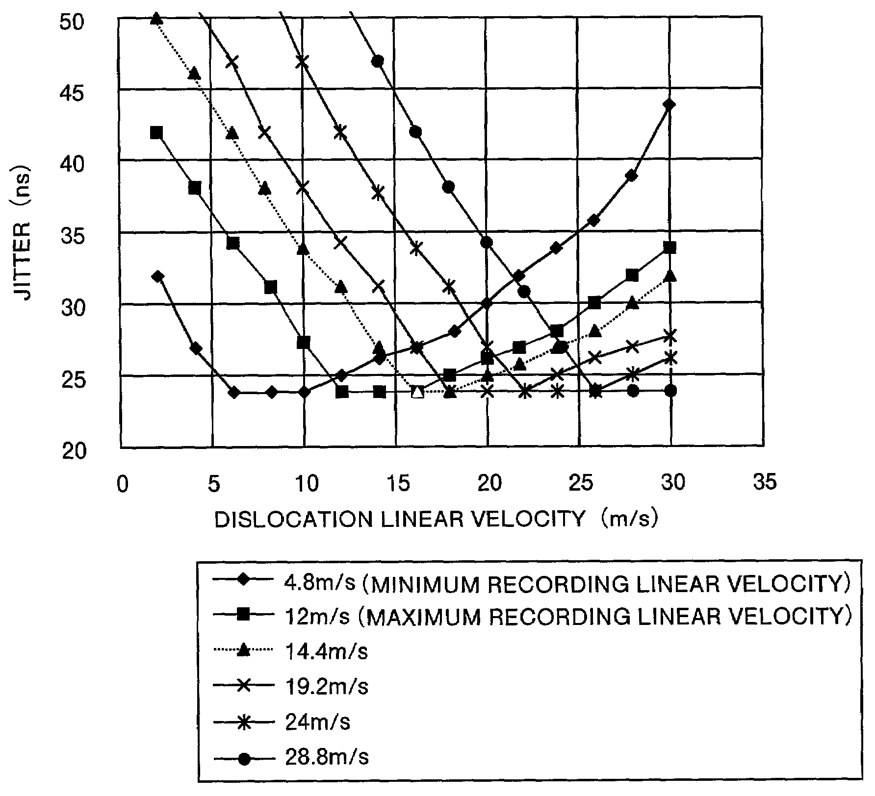
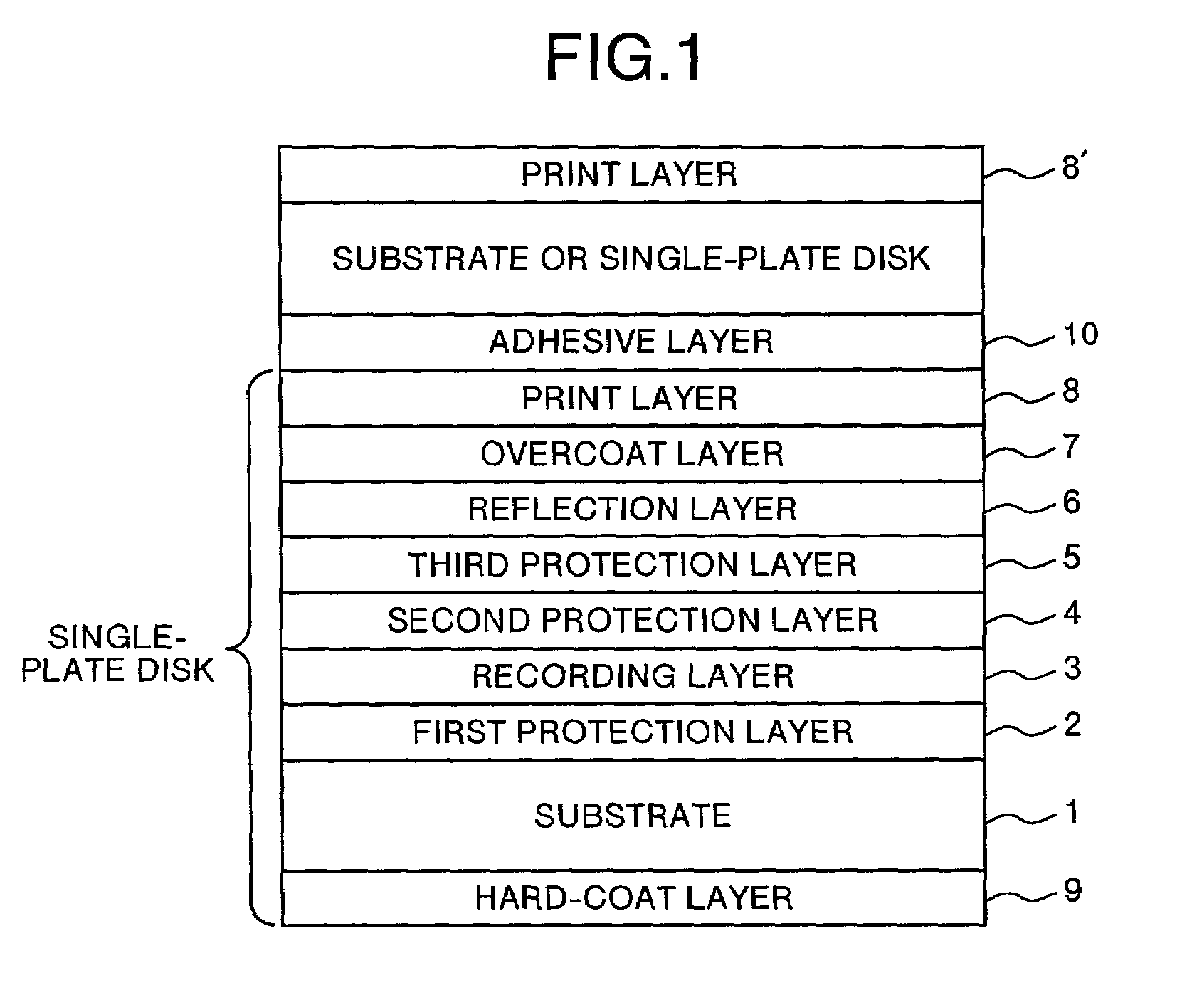
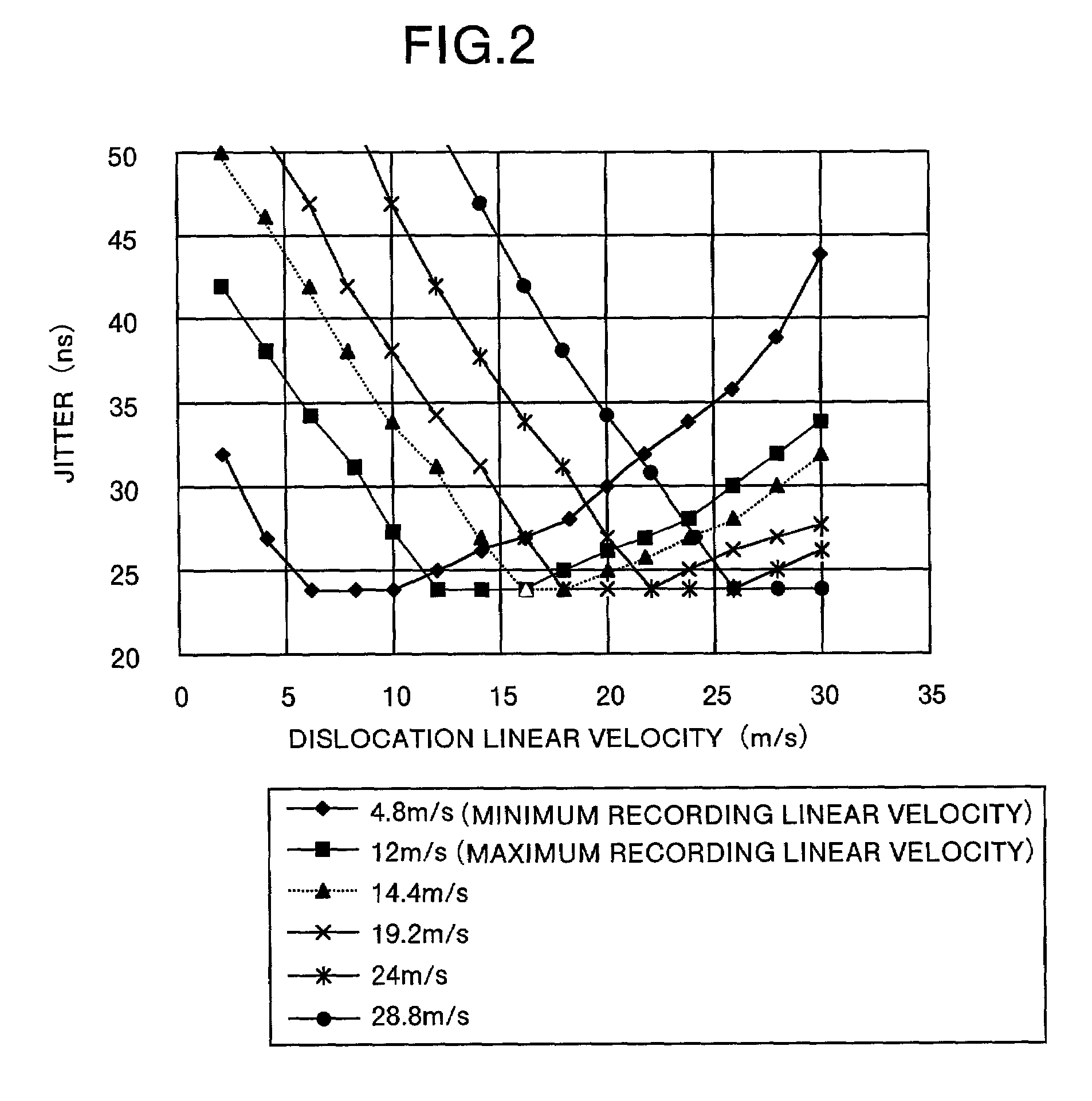
[0151]A polycarbonate substrate 1 having a guide groove with a width of 0.55 μm and depth of 30 nm was prepared by injection molding. On this substrate 1, the first protection layer 2, recording layer 3, second protection layer 4, and the reflection layer 6 were laminated in this order using the sputtering method. The substrate 1 was put into the sputtering unit by keeping the substrate at 55° C. Information that the maximum recording linear velocity is ten times (i.e. 12 m / s) the speed of the CD was recorded onto the substrate 1.

[0152]The first protection layer 2 and the second protection layer 4 were made from ZnS.SiO2. The first protection layer 2 had a thickness of 90 nm and the second protection layer had a thickness of 30 nm. The recording layer 3 was made from Ge2In8Sb68Te22. The recording layer 3 was made 16 nm thick. The reflection layer 6 was made from AlTi (with Ti content of 0.5 weight percent). The reflection layer 6 had a thickness of 140 nm.

[0153]As a result, a lamina...

example 2

[0161]A polycarbonate substrate 1 having a guide groove with a width of 0.2 μm and depth of 27 nm was prepared by injection molding. On this substrate 1, the first protection layer 2, recording layer 3, second protection layer 4, third protection layer 5, and the reflection layer 6 were laminated in this order using the sputtering method . The substrate 1 was put into the sputtering unit by keeping the substrate at 55° C. Information that the maximum recording linear velocity is 8.44 m / s the speed of the CD was recorded onto the substrate 1.

[0162]The first protection layer 2 and the second protection layer 4 were made from ZnS.SiO2. The first protection layer 2 had a thickness of 75 nm and the second protection layer had a thickness of 10 nm. The third protection layer 5 was made from SiC. The third protection layer 5 had a thickness of 3 nm. The recording layer 3 was made from Ag0.5Ge1.5Ga8Sb68Te22. The recording layer 3 had a thickness of 14 nm. The reflection layer 6 was made fro...

examples 3 to 14

[0171]A polycarbonate substrate 1 was prepared by injection molding. On this substrate 1, the first protection layer 2, recording layer 3, second protection layer 4, third protection layer 5, and the reflection layer 6 were laminated in this order using the sputtering method.

[0172]The first protection layer 2 and the second protection layer 4 were made from ZnS.SiO2. The first protection layer 2 had a thickness of 80 nm and the second protection layer had a thickness of 10 nm. The third protection layer 5 was made from SiC. The third protection layer 5 had a thickness of 5 nm. The recording layer 3 was made from material having a composition shown in Table 1 to obtain Examples 3 to 14. The recording layer 3 had a thickness of 15 nm. The reflection layer 6 was made from Ag. The reflection layer 6 had a thickness of 140 nm.

[0173]As a result, a laminate having a layer structure as follows was formed. That is, the substrate 1 (composition: polycarbonate), first protection layer 2 (compo...


PUM

PropertyMeasurementUnit
linear velocityaaaaaaaaaa
depthaaaaaaaaaa

Abstract

An optical information recording medium is provided. This medium at least stores information that indicates a maximum recording linear velocity Vh. The medium comprises a substrate having a concentric circular guide groove. This guide grove has land portions and groves portions. At least a phase change type recording layer is formed on the substrate. The recording layer has such a composition and thickness that a dislocation linear velocity V satisfies the relation V≧Vh×0.85.

Description

FIELD OF THE INVENTION[0001]The present invention relates to a phase change type optical information recording medium capable of recording / reproducing information and capable of rewriting information, by generating a phase change in a recording layer material through the irradiation of a laser beam onto this recording medium. This invention particularly relates to a phase change type optical information recording medium capable of recording information at high speed. This invention further relates to a method of manufacturing the optical information recording medium according to the present invention, a method of and an apparatus for recording / reproducing optical information onto / from the optical information recording medium according to the present invention.BACKGROUND OF THE INVENTION[0002]As one of optical information recording media capable of recording information (“recording”), reproducing information (“reproducing”), and erasing information (“erasing”) based on an irradiation...

Claims


Application Information

Patent Timeline
Patent Type & Authority Patents(United States)
IPC IPC(8): G11B7/24G11B7/004G11B7/0045G11B7/005G11B7/006G11B7/007G11B7/125G11B7/126G11B7/243G11B7/254G11B7/257G11B7/26G11B19/12G11B19/26G11B20/08G11B20/10
CPCG11B7/00454G11B7/0052G11B7/006G11B7/007G11B7/126G11B7/24G11B7/243G11B7/26G11B19/12G11B19/26G11B20/08G11B20/10G11B7/0062G11B7/257G11B2007/24314G11B2007/24316Y10S430/146
Inventor YAMADA, KATSUYUKINARUMI, SHINYAHARIGAYA, MAKOTOTANI, KATSUHIKOIWATA, NORIYUKIONAGI, NOBUAKIITO, KAZUNORISHIBAGUCHI, TAKASHIHIBINO, EIKOYUZURIHARA, HAJIMEOHKURA, HIROKOSHIMOFUKU, AKIRANAKAMURA, YUKI
Owner RICOH KK
Why Eureka
Try Eureka