Valve lash adjuster having electro-hydraulic lost-motion capability

a technology of electrohydraulic loss and valve lash, which is applied in the direction of engines, mechanical equipment, machines/engines, etc., can solve the problems of inability to predict or control the ignition of the inability to easily apply camshaft phasers to si engines, and the inability to achieve a very high degree of certainty, so as to reduce the required strength and size of solenoid, the effect of small diameter passages and cleaner operation

Inactive Publication Date: 2009-03-31
DELPHI TECH INC
View PDF6 Cites 26 Cited by
  • Summary
  • Abstract
  • Description
  • Claims
  • Application Information

AI Technical Summary

Benefits of technology

[0018]In each approach, an electrically controlled solenoid valve within the DHLA assembly diverts hydraulic fluid between support and non-support of a piston slidably disposed in an elongated housing and terminating in a ball head. The geometry for the valve is such that the valve pin is force-balanced, thus reducing significantly the required strength and size of solenoid relative to the prior art solenoid and valving.
[0019]The preferred hydraulic fluid is diesel fuel which is readily available in a diesel engine from the low-pressure fuel supply pump for the engine fuel rail, which fuel preferably is used to lubricate the entire “top end” of the engine. Relatively dirty, carbon-contaminated engine lubricating oil is relegated to lubricating only the engine crankshaft and cylinder bores. The continuously refreshed and very much cleaner diesel fuel is used to lubricate the camshaft bearings and valve train, with conventional seals providing segregation of the two fluids. It is understood that the lubricity of diesel fuel is less than that of lubricating oil, however there is a clearly defined minimum standard for lubricity against which the bearing surfaces may be designed. Use of diesel fuel rather than engine lubricating oil allows for substantially smaller diameter passages and cleaner operation than in prior art systems. The use of smaller passages reduces very significantly the amount of fluid to be diverted between operating modes, eliminating the need for an accumulator chamber and accumulator piston as in the prior art.

Problems solved by technology

However, camshaft phasers, while readily applied to SI engines, are not as suitable for CI engines since cam phasing introduces the risk of catastrophic valve-to-piston collisions due to the close proximity of the piston crown to the cylinder head at top dead center (TDC) at which point the valves are obliged to be closed.
Thus, in the prior art the exact point in the compression stroke at which the compressed charge in a cylinder will ignite cannot easily be predicted or controlled to a very high degree of certainty, and in practice the cylinders of a multiple-cylinder HCCI engine may not fire with a degree of uniformity required to meet future performance standards.
Serious drawbacks of such known VVA / VVT systems are that they employ engine lubricating oil as the hydraulic medium, which tends to be dirty, carbon-laden and relatively high viscosity, requiring relatively large passageways to prevent flow failure; they employ a relatively bulky, powerful solenoid control valve which because of its size has a relatively slow speed of response; and they introduce significant additional complexity to the cylinder head that, in so doing, creates problematic packaging and manufacturing issues.

Method used


Image

  • Valve lash adjuster having electro-hydraulic lost-motion capability
  • Valve lash adjuster having electro-hydraulic lost-motion capability
  • Valve lash adjuster having electro-hydraulic lost-motion capability

Examples


embodiment 300

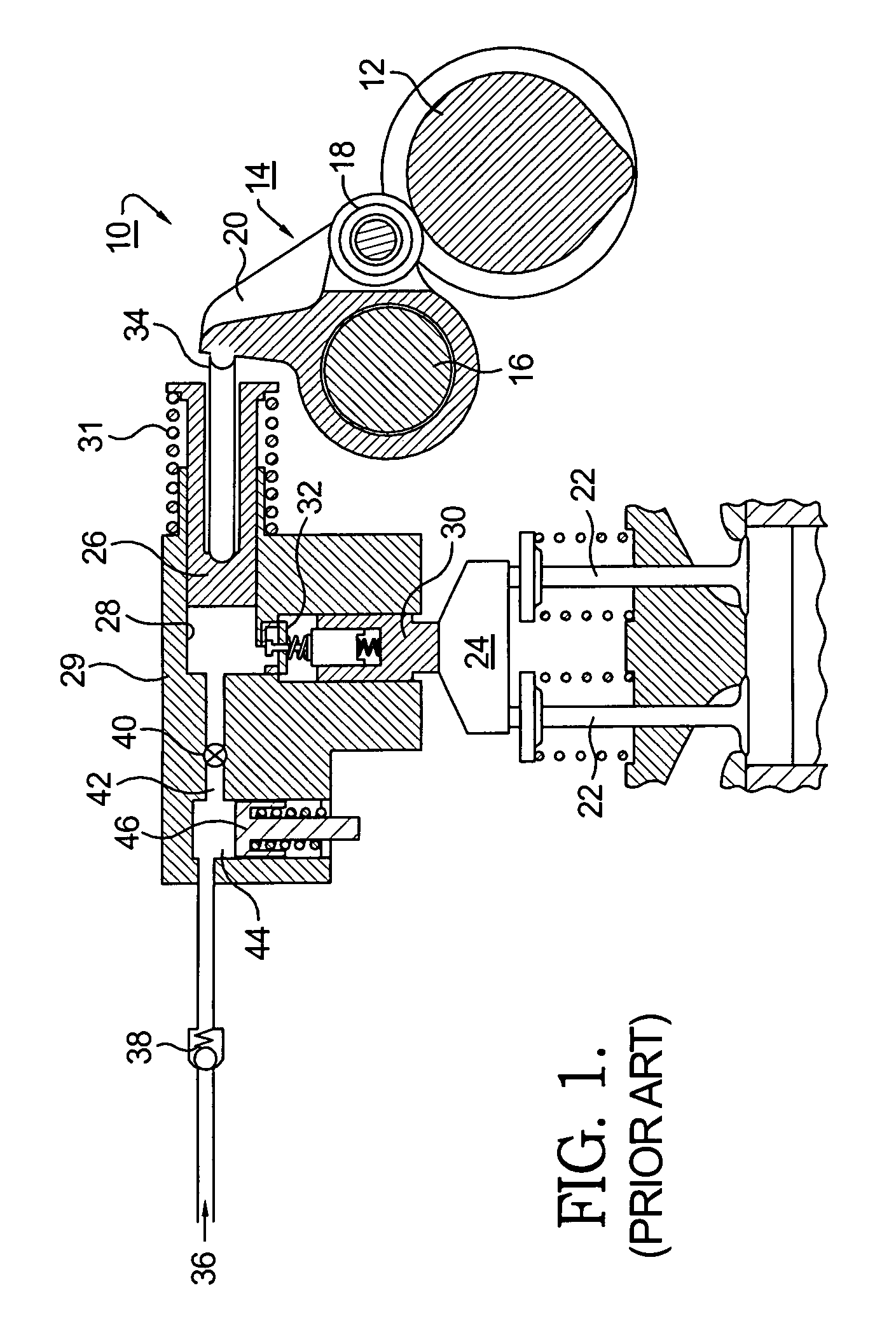
[0054]In the prior art, a comparable Type 3 rocker arm is an inflexible unit wherein rotary motion of the cam is translated faithfully into reciprocal motion of the valve stem. Prior art lash adjustment typically is provided by either a screw head (not shown) on valve stem 94 or a hydraulic valve lifter (HVL) assembly (not shown) disposed between arm 320 and valve stem 94. In HLA embodiment 300, rocker arm assembly 314 is provided as first and second arms 320, 322 independently and rotatably mounted on shaft 316. First arm 320 is adapted to engage valve stem 94.

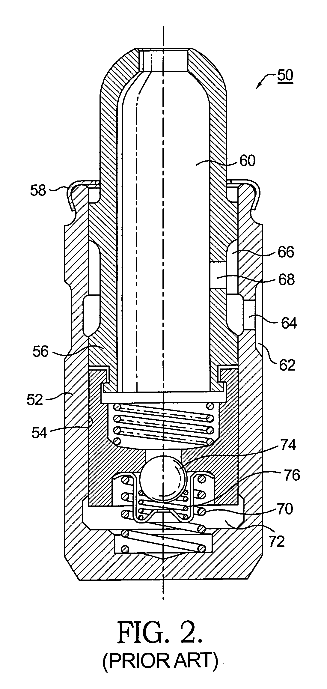
[0055]A well 380 is provided in second arm 322. HLA 300 is disposed in well 380 and is provided with hydraulic fluid, for example, engine oil, via an axial gallery 324 in shaft 316 and a radial passage 325 extending to a connector drilling 326 in arm 322 that communicates with HLA 300. As shown in the exemplary assembly in FIG. 6, HLA 300 is substantially identical in arrangement with HLA 50 shown in FIG. 2, and those compone...

embodiment 400

[0058]In DHLA embodiment 400, rocker arm assembly 414 is provided as first and second arms 420, 422 independently and rotatably mounted on shaft 416. First arm 420 is adapted to engage valve stem 94 as described further below, and second arm 422 is supportive of cam follower roller 417. A well 480 in second arm 422 is analogous to well 380 in FIG. 6. DHLA 300 is disposed in well 480 and is provided with hydraulic fluid, preferably in the form of diesel fuel oil, via an axial gallery 424 in shaft 416 and a radial passage 425 extending to a connector drilling 426 in arm 422 that communicates with DHLA 400. As shown in the exemplary assembly in FIG. 6a, DHLA 400 is substantially identical in arrangement and function with DHLA 200 shown in FIG. 5, and those components need not be repeated here save to note that the overall size of DHLA 400 may be significantly smaller than DHLA 200.

[0059]First arm 420 is provided with a buttress 428 having a wear surface 430 for receiving the spherical ...

first embodiment

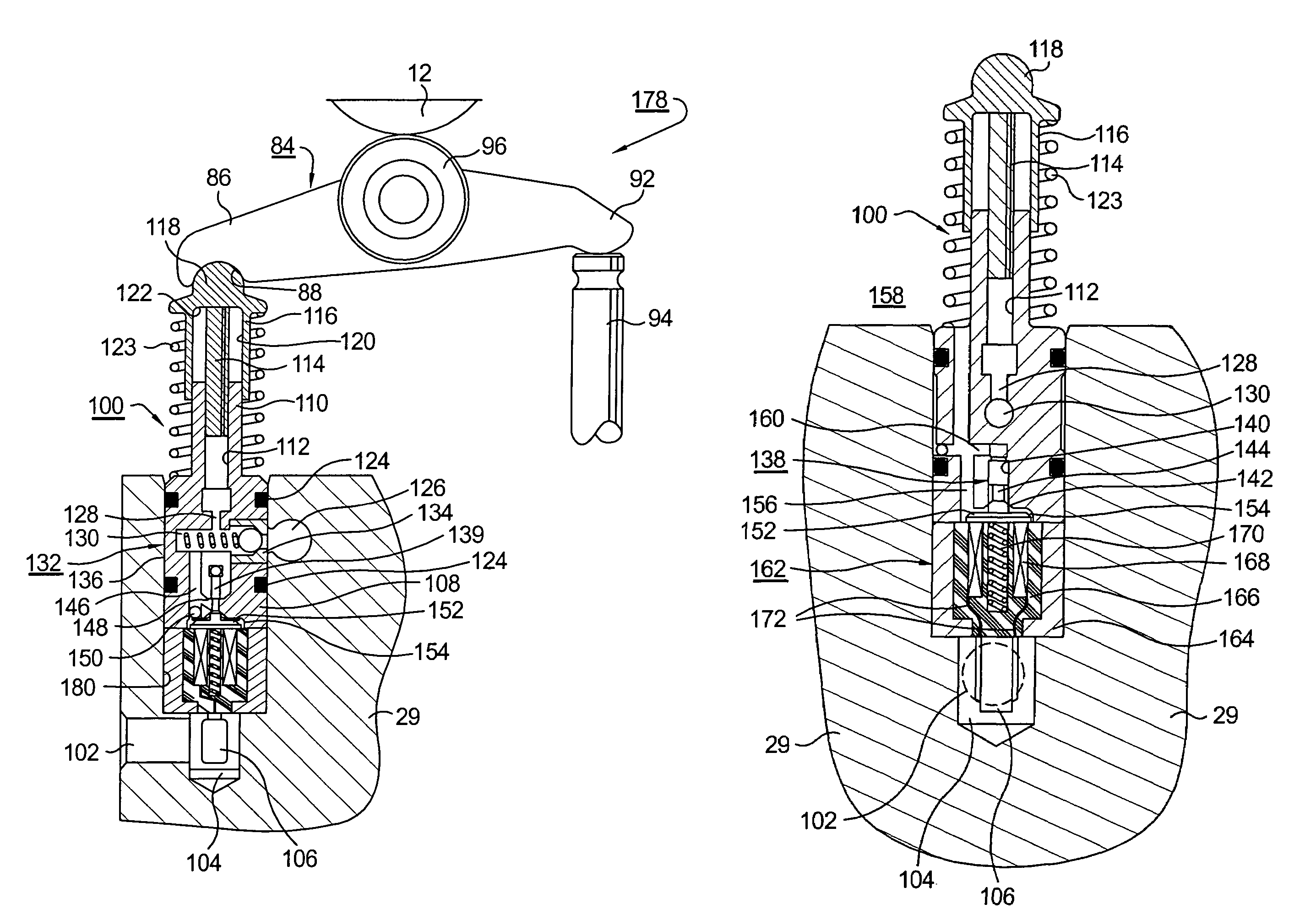
[0072]The details of lost-motion control valve 638, armature 652 and solenoid stator assembly 662 are identical to valve, armature and stator assembly 138, 152 and 162, as described in the first embodiment, and need not be described again.

[0073]In operation, in valve-activating mode, as DHLA 600 expands like a conventional HLA to provide a pivot point on which rocker arm assembly 614 pivots to cause the engine valve to open, all mechanical lash in valve train 678 between camshaft pushrod 603 and valve stem 94 is eliminated. In operation in valve-deactivating lost-motion mode of DHLA 600, control valve 638 is opened by energizing of solenoid assembly 662, allowing collapse of piston 616 into body 608 in lost motion in response to raising of pushrod 604 by the camshaft. Valve stem 94 is not actuated and the associated engine valve is not opened.


PUM


Abstract

In a Type 2 engine, a valve deactivation hydraulic lash adjuster (DHLA) in accordance with the invention replaces a conventional hydraulic lash adjuster in the train of a gas-exchange valve in a compression-ignited engine. In a Type 3 engine, a similar DHLA is disposed within an articulated rocker arm which is made selectively competent (valve activating) or incompetent (valve deactivating) thereby. A solenoid valve within the assembly diverts hydraulic fluid between support and non-support of a piston slidably disposed in a housing and terminating in a ball head. The valve is force-balanced. The preferred hydraulic fluid is diesel fuel, allowing for smaller diameter passages and cleaner operation than in prior art systems, eliminating the need for an accumulator chamber and accumulator piston as in the prior art. An alternate version of a type 3 engine having a DHLA, in accordance with the invention, is also shown.

Description

TECHNICAL FIELD[0001]The present invention relates to variable valve activation (VVA) and variable valve timing (VVT) mechanism for internal combustion engines; more particularly, to VVA / VVT mechanism for modulating the timing of compression ignited (CI) engines such as diesel engines; and most particularly, to a valve lash adjuster having electro-hydraulic lost-motion capability for varying the lift and / or timing of individual valves in a valve train of a multi-cylinder engine.BACKGROUND OF THE INVENTION[0002]Means for varying the timing of valve actuation of internal combustion engines are well known. Such means typically take the form of a camshaft phaser or an element of a valve train, such as rocker arms, roller finger followers, hydraulic valve lifters, or hydraulic lash adjusters, provided with a mechanism for switching between a valve activating mode and a valve deactivating mode. VVA / VVT is especially well known in spark-ignited (SI) engines, in which it is an essential ele...

Claims


Application Information

Patent Timeline
Patent Type & Authority Patents(United States)
IPC IPC(8): F01L1/14
CPCF01L1/181F01L1/24F01L1/2405F01L13/0005Y10T74/2107F01L2001/188F01L2820/01F01L2820/031F01L2001/186
Inventor DINGLE, PHILIP J. G.
Owner DELPHI TECH INC
Why Eureka
Try Eureka